Vehicle lamp unit

a technology for lamps and vehicles, applied in the direction of lighting and heating apparatus, coupling device connections, lighting support devices, etc., can solve the problems of water entering the joint, poor maintenance workability,

Inactive Publication Date: 2001-09-18
YAZAKI CORP
View PDF3 Cites 9 Cited by
  • Summary
  • Abstract
  • Description
  • Claims
  • Application Information

AI Technical Summary

Problems solved by technology

In the prior art, the branch lines 8 arranged on the rear surface of the frame 2 become hindrance to the exchange of the bulbs 9, resulting

Method used


Image

  • Vehicle lamp unit
  • Vehicle lamp unit
  • Vehicle lamp unit

Examples


Embodiment Construction

The following is a detailed description of one embodiment of the present invention, with reference to the accompanying drawings.

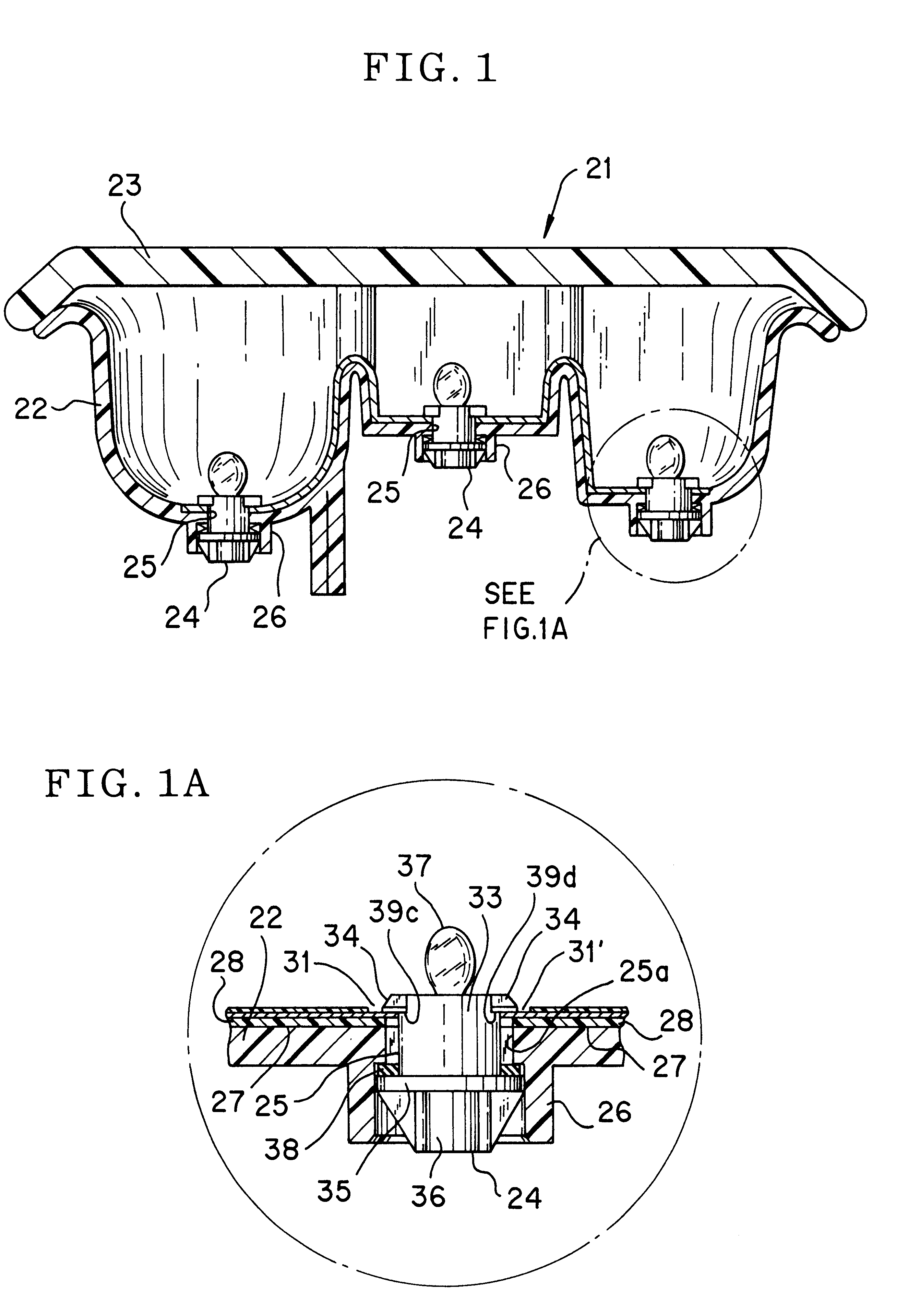
In FIG. 1, reference numeral 21 indicates a rear combination lamp unit (hereinafter referred to as "lamp unit") of a vehicle. The lamp unit 21 comprises a frame 22, a lens 23 attached to the front surface of the frame 22, and a plurality of bulb sockets 24 attached to the rear surface of the frame 22. (Although three of them are shown in FIG. 1, the number is not limited to it.).

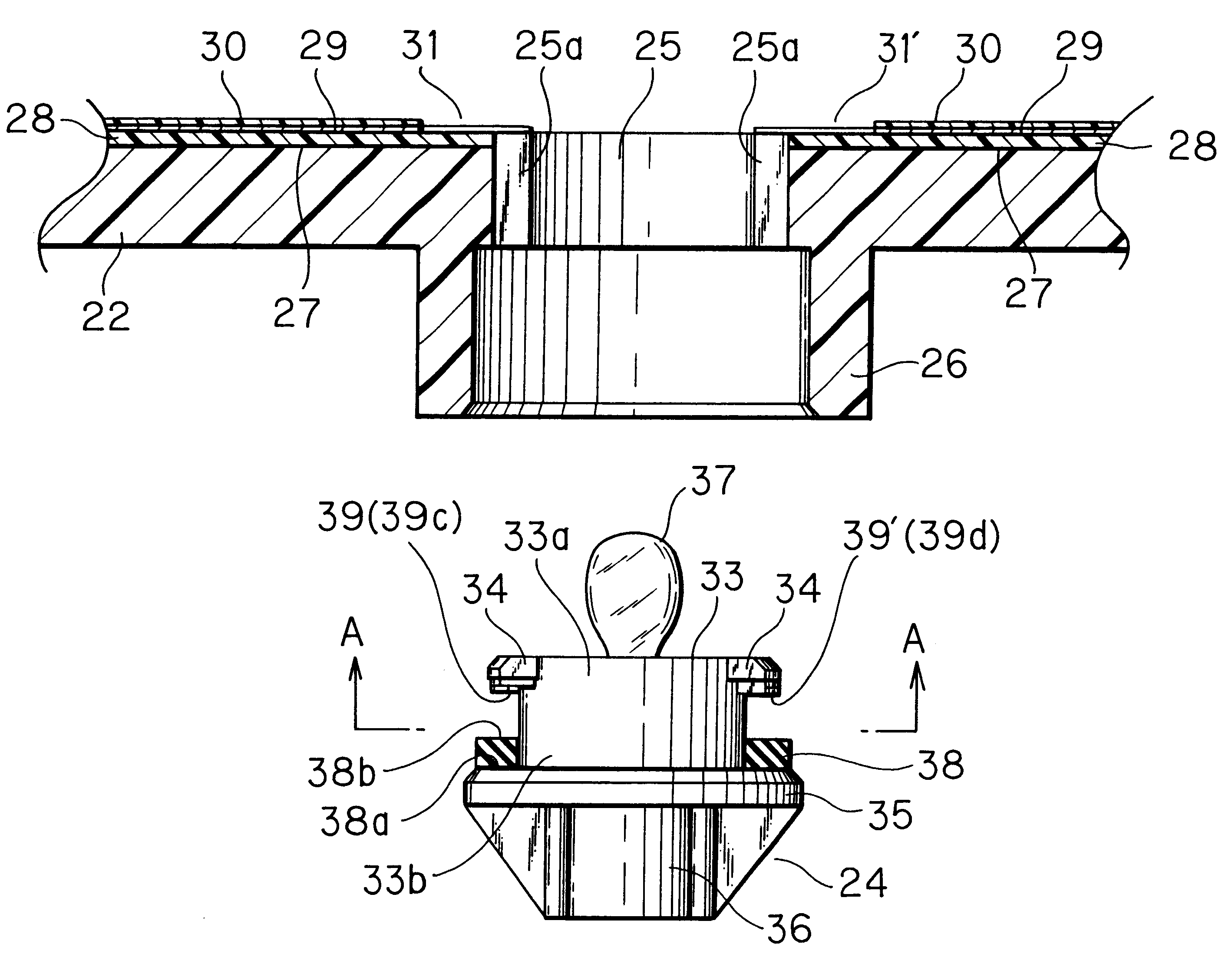
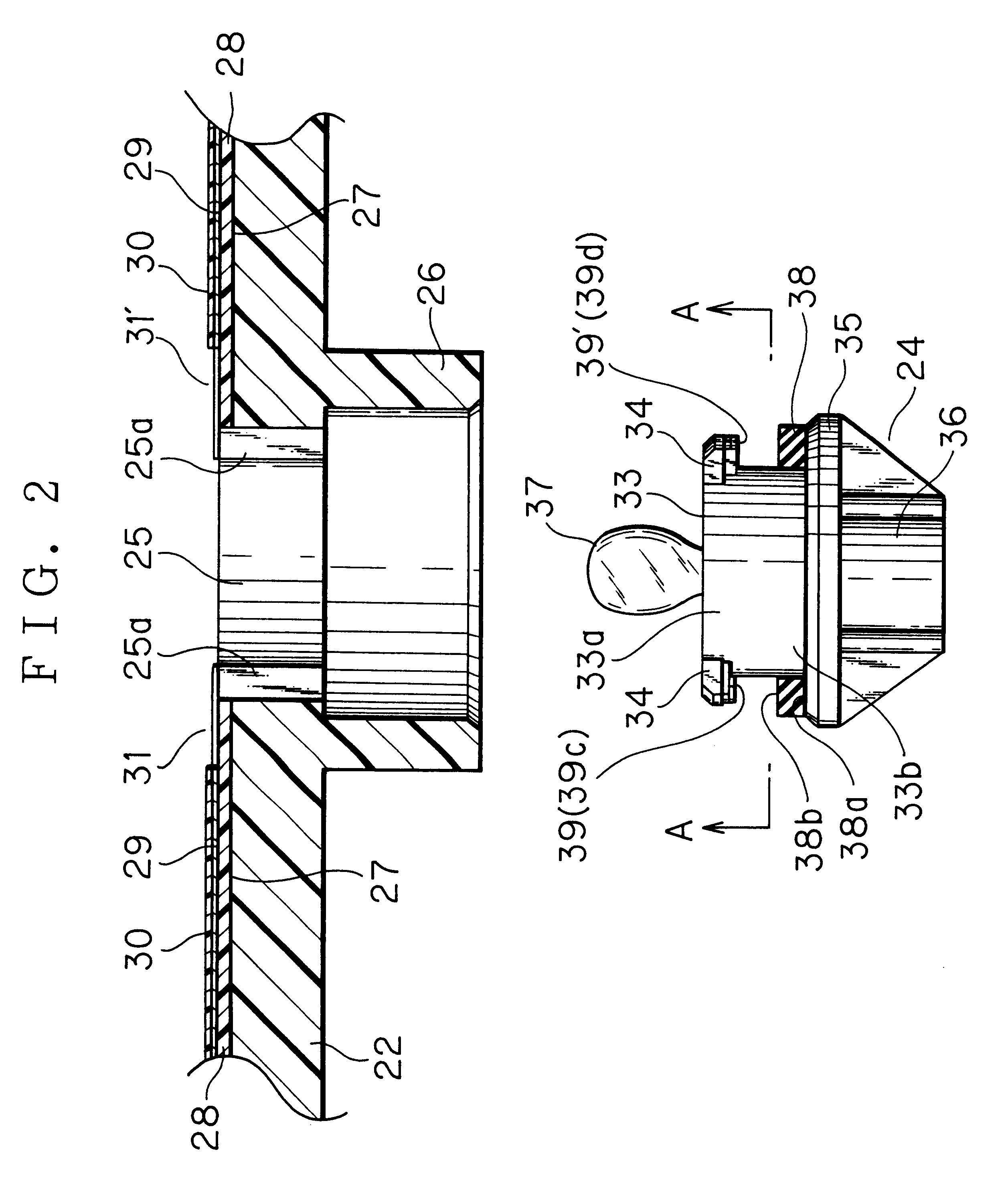
The frame 22 is integrally made of a synthetic resin material, and has three bulb attachment holes 25 for the three bulb sockets 24. Each of the bulb attachment holes 25 is provided with notches 25a (shown in FIGS. 2 and 4). In the vicinity of each bulb attachment hole 25, cylindrical members 26 protrude from the rear surface of the frame 22, i.e., the outer surface of the frame 22.

As shown in FIG. 2, a concave groove 27 is formed on the inner surface of the frame 22, and a belt-lik...


PUM


Abstract

A vehicle lamp unit is provided. The vehicle lamp unit comprises a plurality of bulb sockets each provided with a bulb, and a frame having bulb attachment holes for accommodating the respective bulb sockets. A reflection surface is formed on a surface to be the inner surface of the frame. The bulbs are connected to the reflection surface via the respective bulb sockets, and a flat arranging material as a lighting conductor communicating with electric conductors of the vehicle is disposed on or buried under the reflection surface.

Description

1. Field of the InventionThe present invention relates to a vehicle lamp unit, and more specifically, to a vehicle lamp unit having a lighting conductor for bulb sockets disposed on or buried under a reflection surface formed on a frame.2. Description of the Related ArtIn FIG. 11, a vehicle lamp unit 1 comprises a frame 2, a lens 3 attached to the front surface of the frame 2, and a plurality of bulb sockets 4 (three bulb sockets are shown in FIG. 11) attached to the rear surface of the frame 2.Bulb attachment holes 5 for accommodating the bulb sockets 4 are formed on the frame 2, and a reflection surface is formed on the surface to be the inner surface of the frame 2.Branch lines 8 branched from joint portions 7 of a wire harness 6 are connected to the respective bulb sockets 4, and as shown in FIG. 12, terminals 10 and 11 provided to each edge of the branch lines 8 are in contact with electrodes 9a and 9b of a bulb 9 attached to each of the bulb sockets 4. Reference numeral 12 ind...

Claims


Application Information

Patent Timeline
IPC IPC(8): B60Q1/26F21S8/10F21V19/00H01R33/05H01R33/18
CPCB60Q1/2607F21S48/20H01R33/18F21S48/212H01R2201/26F21S43/195F21S43/31
Inventor SUZUKI, TAKAHIKOWATANABE, HIROSHI
Owner YAZAKI CORP
Why Eureka
Try Eureka