

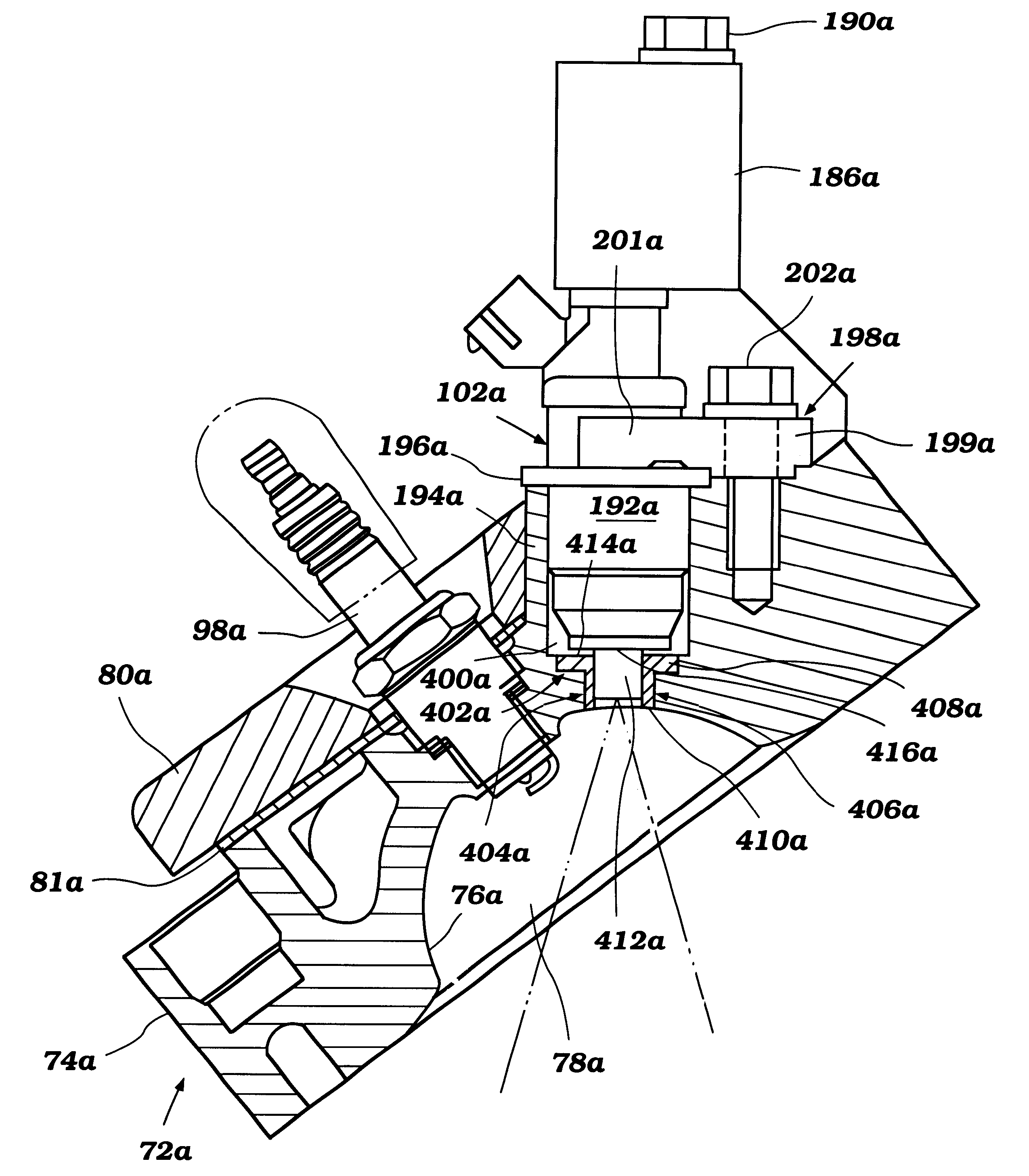
Injector mounting arrangement for direct-injected engines
a technology for injectors and engines, applied in the direction of machines/engines, liquid fuel feeders, mechanical devices, etc., can solve the problems of reducing the sealability of the assembly, affecting the performance of the engine, and affecting the operation of the engin
- Summary
- Abstract
- Description
- Claims
- Application Information
AI Technical Summary
Benefits of technology
Problems solved by technology
Method used
Image

Examples
Embodiment Construction
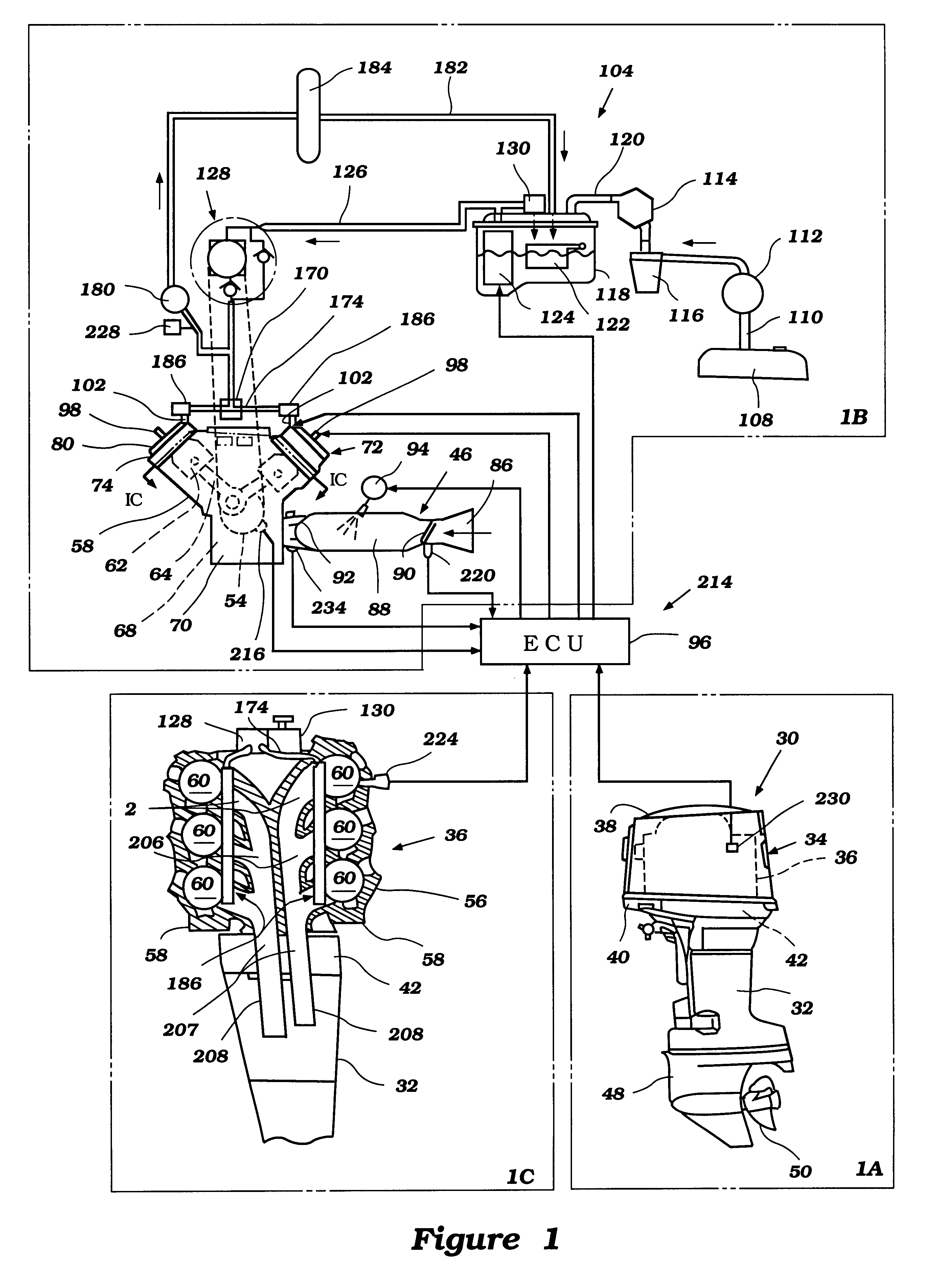
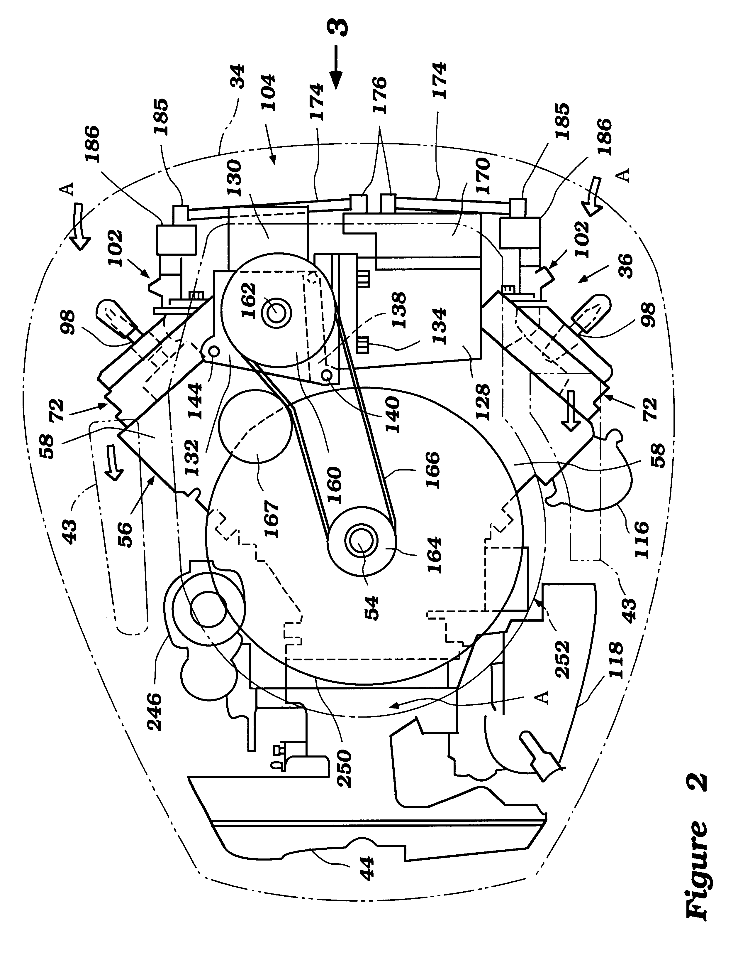
With initial reference to FIG. 1, an outboard motor employing a two-stroke engine will be generally described to provide an environment in which the present fuel injector mounting arrangement is practiced. To aid the discussion, FIG. 1 has been divided with phantom lines into three portions: 1a, 1b and 1c. While the present invention is illustrated in the context of a two-cycle outboard motor, it is anticipated that certain aspects of the present invention can be used in other environments. For instance, FIG. 13 will illustrate a four-cycle engine with which the present invention can be used. In addition, other engines for marine propulsion systems, such as stem drive systems, for land vehicles, such as motorcycles and automobiles, and for utility machines, such as lawn mowers, can also benefit from various features, aspects and advantages of the present invention. Moreover, the present invention can also be used with stationary engines, such generator motors or the like.
With refere...
PUM
 Abstract
Description
Claims
Application Information