Pointing apparatus

a technology of pointing apparatus and pointing table, which is applied in the direction of instruments, computing, electric digital data processing, etc., can solve the problems of not being able to seamlessly point the user, the user cannot do exclusively those virtual world tasks in videos projected on the work desk, and the projector cannot project high-quality images of such complex virtual world screens as graphical user interfaces

Inactive Publication Date: 2001-10-02
NEC CORP
View PDF14 Cites 97 Cited by
  • Summary
  • Abstract
  • Description
  • Claims
  • Application Information

AI Technical Summary

Benefits of technology

The present invention generally seeks to solve the problems associated with a prior art described above. It is an object of the present invention to provide a pointing apparatus which allows the user to directly point not only to a virtual world displayed on a display unit but also to real world objects such as documents or three-dimensional objects in the real world.

Problems solved by technology

However, existing projectors cannot project high-quality images of such complex virtual world screens as graphical user interfaces.
Even if a high definition projector is developed, it is very questionable whether the user can do exclusively those virtual world tasks in videos projected on the work desk.
The technology does not allow the user to seamlessly point to a virtual world on the display and a real world outside the display.
As a matter of fact, the technology does not take such a concept into consideration at all.

Method used


Image

  • Pointing apparatus
  • Pointing apparatus
  • Pointing apparatus

Examples


examples

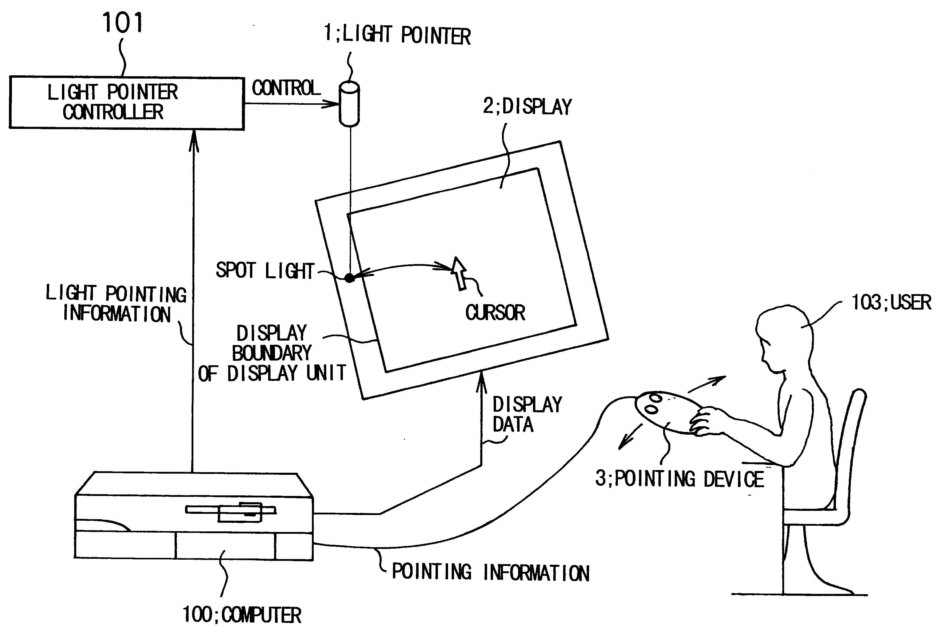
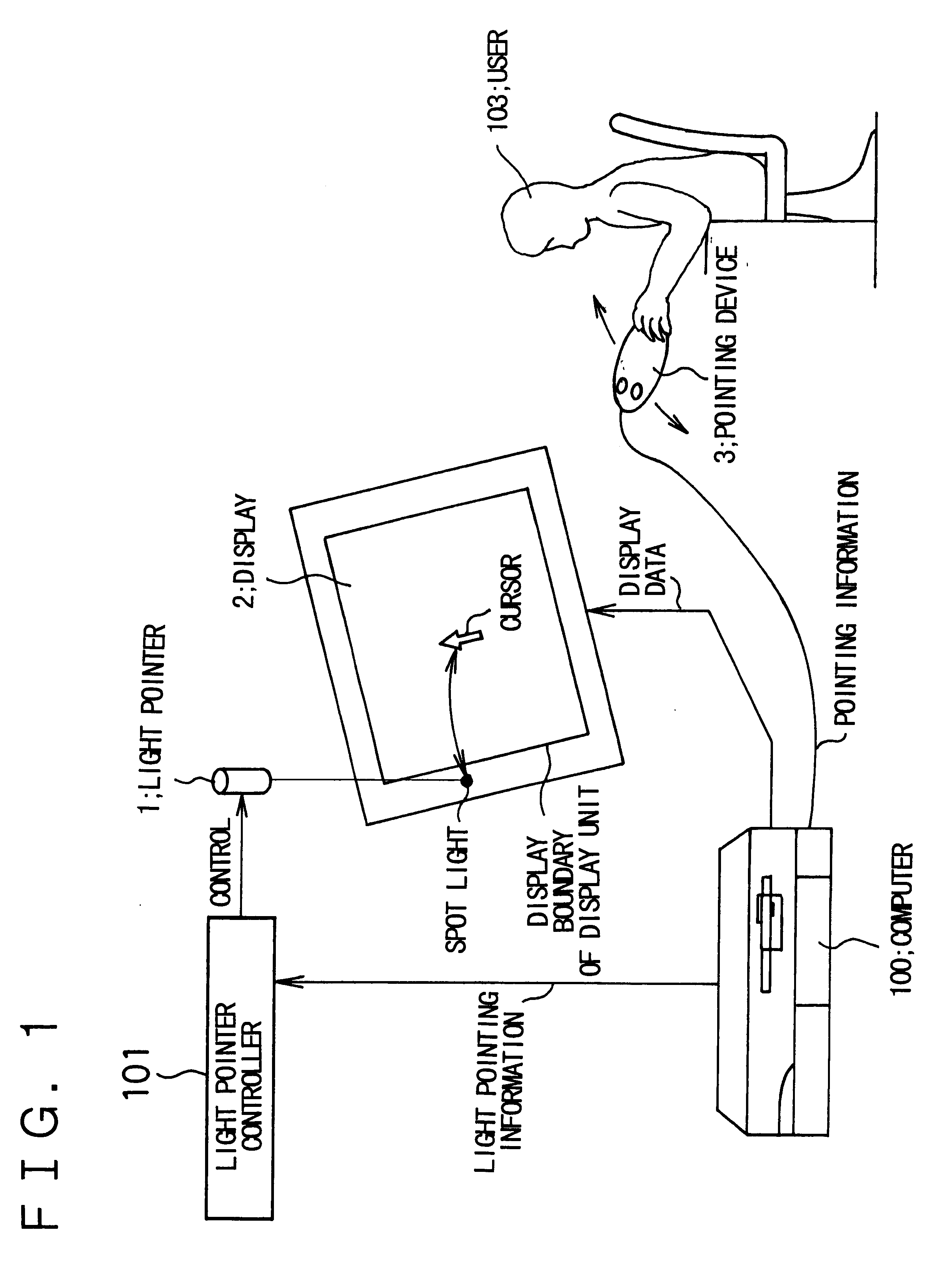
FIG. 1 is a diagram showing the configuration of a first embodiment according to the present invention. Referring to FIG. 1, the first embodiment comprises a light pointer 1 capable of projecting a desired-shaped light beam on a real object in the real world at a desired position or in a desired direction, a display 2 on which virtual world objects such as graphical user interfaces or electronic data are displayed, a pointing device 3 manipulated by a user 103 to point to a desired position, light pointer controller 101 for controlling the light pointer 1, and a computer 100 to which the light pointer controller 101, display 2 and pointing device 3 are connected (or communicated) via predetermined interfaces. The computer 100 comprises CPU, memories, disk units and other peripheral devices upon needs.

The light pointer 1 can project a desired-shaped light beam on an object at or onto a desired position or in a desired direction. The light beam should be intensive enough for the user ...

first embodiment

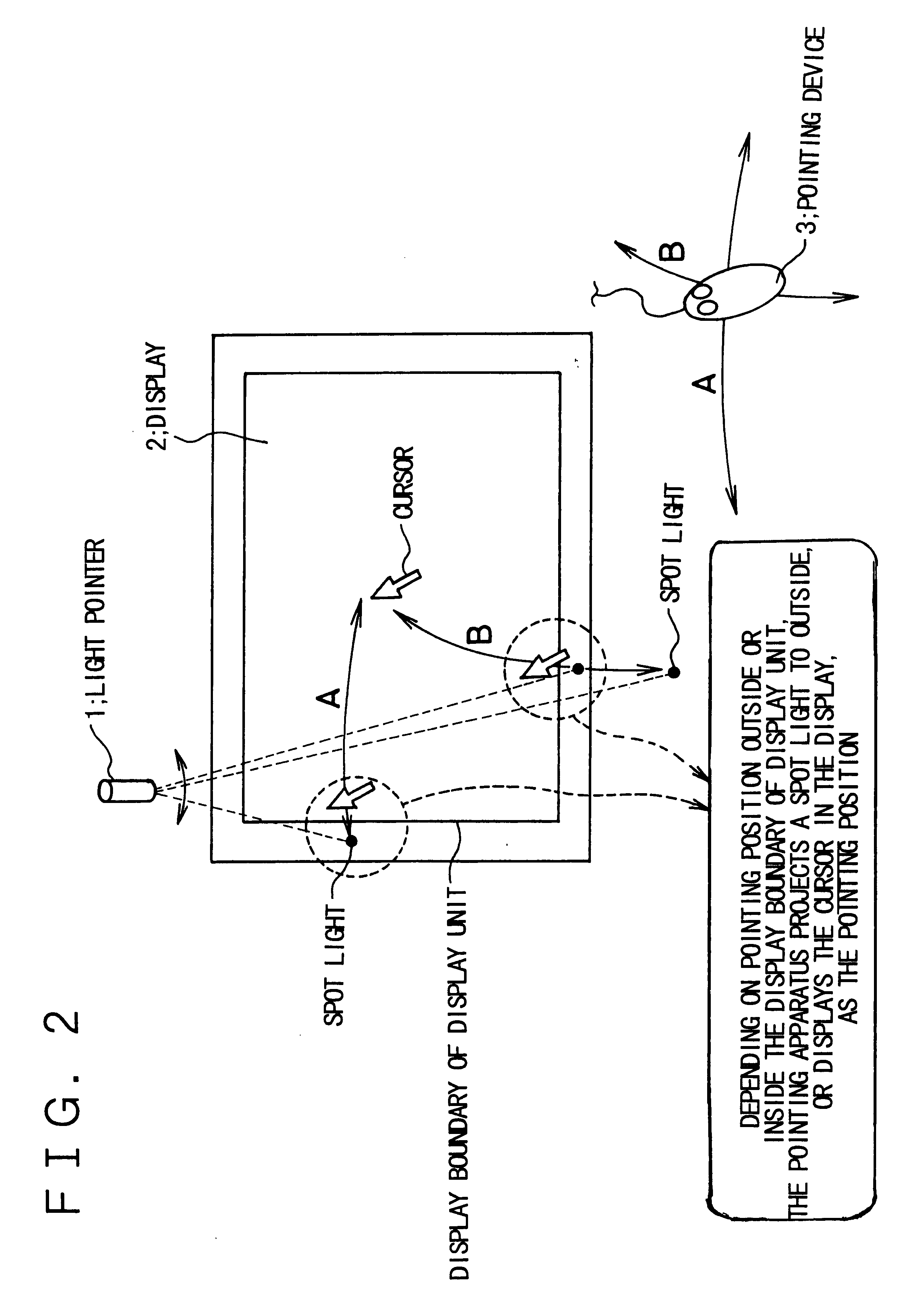
When the user moves the pointing device 3 in the direction indicated by arrow B, the boundary between the virtual world and the real world is not the boundary detected by the boundary detection sensor 4 but the boundary of the display area on the display 2. Therefore, in this case, the user can point to a position on the display 2 with the cursor, and point to a position on the real object (i.e., here, outside the display area) with the pointer light beam, across the boundary of the display area on the display 2 as in the first embodiment described above.

The detection method of the boundary detection sensor 4 depends on a real object to be detected. For example, when the real object is a document as shown in FIG. 4 or FIG. 5, a photoelectric switch may be provided on the frame of the display 2 to detect whether paper is placed. A one-dimensional or two-dimensional image sensor may also be used. The boundary detection method is not detailed here because it does not relate directly to...

fourth embodiment

FIG. 6 is a diagram showing the configuration of the present invention. Referring to FIG. 6, a light pointer 1 capable of projecting a desired-shaped pointer projection light beam at a desired position on the work desk at which the user works, a built-in display 10 built in the working surface of the work desk, a pointing device 3 used to operate the pointer projection light beam projected from the light pointer 1 and the position of the cursor on the built-in display 10, a camera 11 capable of monitoring objects on the work desk, a reflecting mirror 12 provided on the work desk, light pointer controller 101 for controlling the light pointer 1, boundary determination means 102 for determining the boundary between the display screen of the built-in display 10 and the document on the work desk based on image data sent from the camera 11, and a computer 100 controlling the whole system.

The built-in display 10 may be a liquid crystal display or a projection-type projector built in the w...


PUM


Abstract

The present invention provides a precise, easy to understand pointing apparatus. It allows users to point both to a position on a display on which virtual world information is displayed and to real objects in the real world with one pointing device to increase productivity. The pointing apparatus comprises, for example, a light pointer capable of projecting a desired-shaped pointer light beam on a real object in the real world, such as a document or a three-dimensional object, at a desired position or in a desired direction, a display on which virtual world objects such as a graphical user interface or electronic data are displayed, a pointing device allowing the user to point to a desired position, and a boundary detection sensor detecting the position of the real object and sensing the boundary between the real object and the display area of the display. The pointing apparatus displays a cursor when the user points to a position on the display, while it displays the pointer light when the user points to the real object. This ability allows the user to point to both a position in the virtual world and a position in the real world with one pointing device.

Description

The present invention relates to a pointing apparatus, and more particularly to a pointing apparatus which allows users to point to an object and to specify coordinates while moving freely between the virtual space displayed on a display and the real world space in which real objects exist.First, an overview of the present invention will be described. The pointing apparatus according to the present invention allows the user to point not only to objects in the virtual world displayed on the display but also to objects in the real world, such as documents or three-dimensional objects. That is, the present invention relates to an user interface, called "Augmented Reality", created by combining (or making continuously) the real world with the virtual world.The description of the related art of the present invention begins with the description of "Augmented Reality", followed by the description of related known arts."Augmented Reality" (hereinafter called "AR"), a concept introduced in 1...

Claims


Application Information

Patent Timeline
Patent Type & Authority Patents(United States)
IPC IPC(8): G09G5/08G06F3/033G06F3/048G06F3/038G06F3/0481
CPCG06F3/033G06F3/038G09G5/08
Inventor KASHITANI, ATSUSHI
Owner NEC CORP
Why Eureka
Try Eureka