
Suspension stop for an agricultural vehicle

a technology for agricultural vehicles and suspension stops, which is applied in the direction of rigid suspensions, pivoted suspension arms, transportation and packaging, etc., can solve the problem of limiting the permitted rotation range of the front axle about the vehicle longitudinal axis

Inactive Publication Date: 2001-10-09
BLUE LEAF I P INC
View PDF5 Cites 4 Cited by
  • Summary
  • Abstract
  • Description
  • Claims
  • Application Information

AI Technical Summary

Benefits of technology

According to the present invention, there is provided an agricultural vehicle having a front axle mounted on a suspension in a manner that permits the front axle to move up and down in relation to the vehicle body and to pivot about the vehicle longitudinal axis so as to allow the wheels on the ends of the axle to move up and down independently.
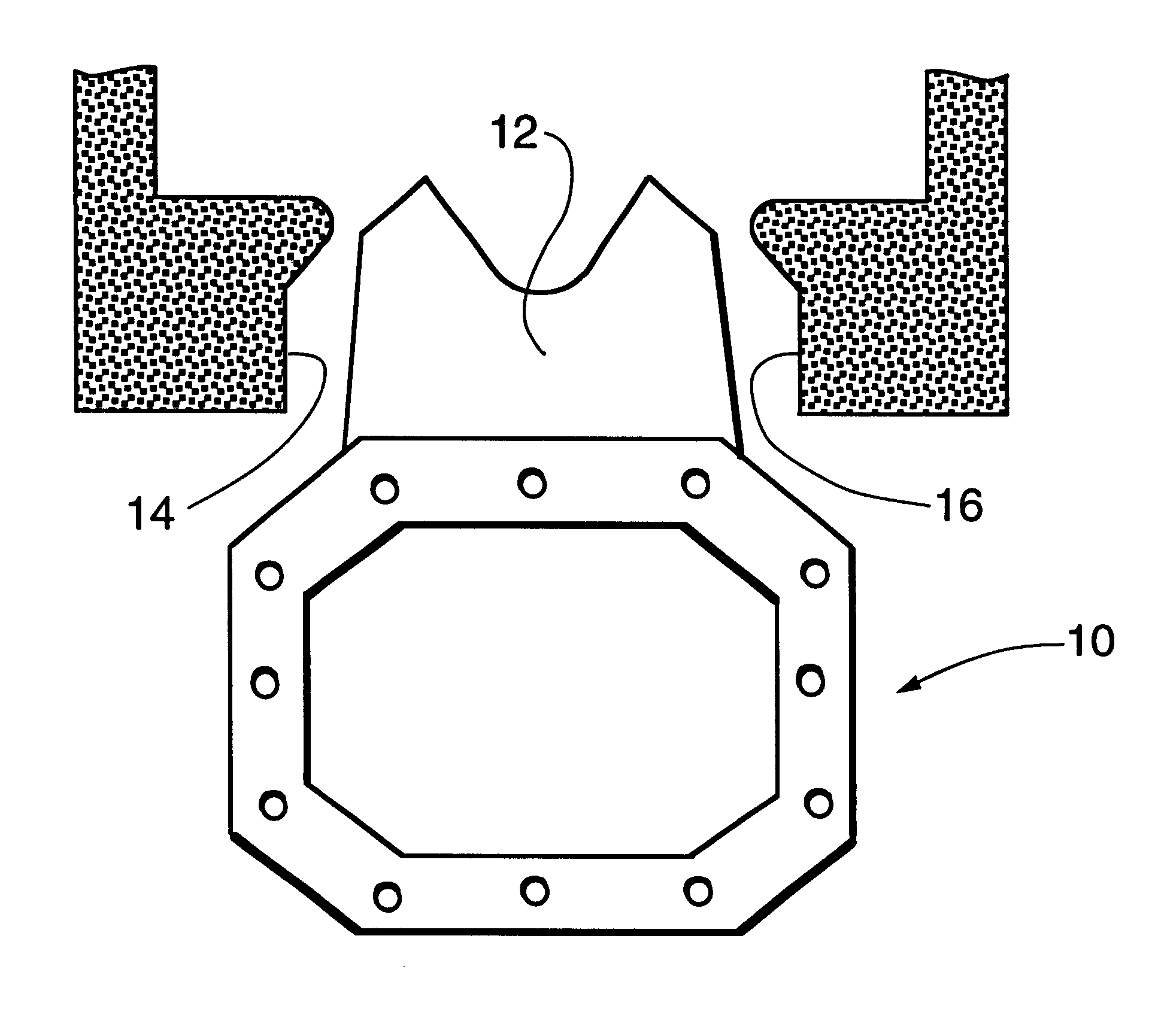
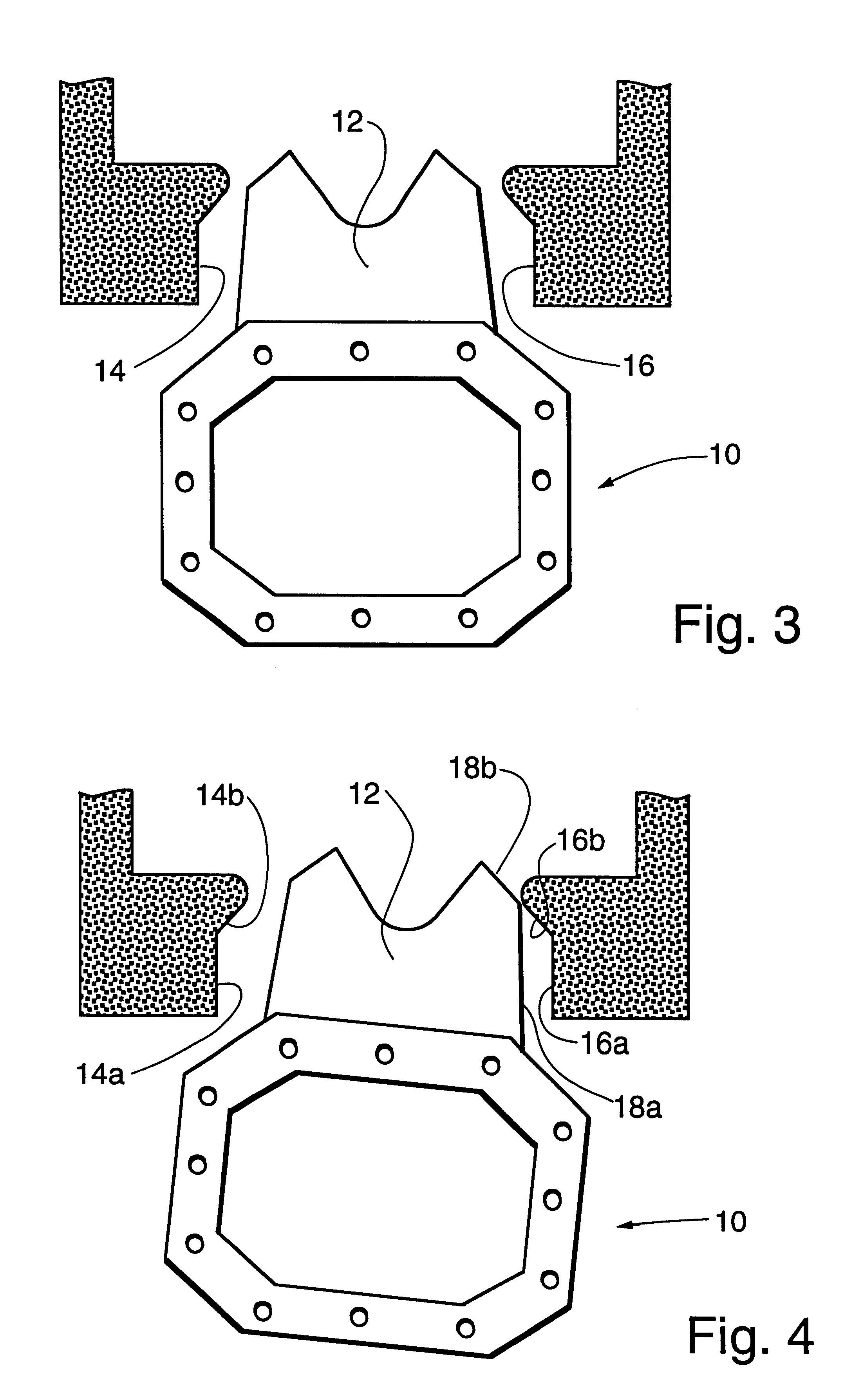
The vehicle is characterized in that the housing of the axle comprises a stop plate that projects vertically upwards towards the vehicle body and the vehicle body comprises abutment surfaces. The abutment surfaces straddle the stop plate and abut the side edges of the stop plate thus limiting the permitted range of rotation of the front axle about the vehicle longitudinal axis.
The abutment surfaces on the vehicle body and the stop plate are preferably so shaped as to minimise the range of rotation of the axle about the vehicle longitudinal axis when the height of the vehicle above the axle is small (e.g. to avoid interference between the steerable wheels and the tractor chassis) and to maximise the range of rotation of the axle about the vehicle longitudinal axis when the height of the vehicle above the axle is large.

Problems solved by technology

The abutment surfaces straddle the stop plate and abut the side edges of the stop plate thus limiting the permitted range of rotation of the front axle about the vehicle longitudinal axis.

Method used


Image

  • Suspension stop for an agricultural vehicle
  • Suspension stop for an agricultural vehicle
  • Suspension stop for an agricultural vehicle

Examples


Embodiment Construction

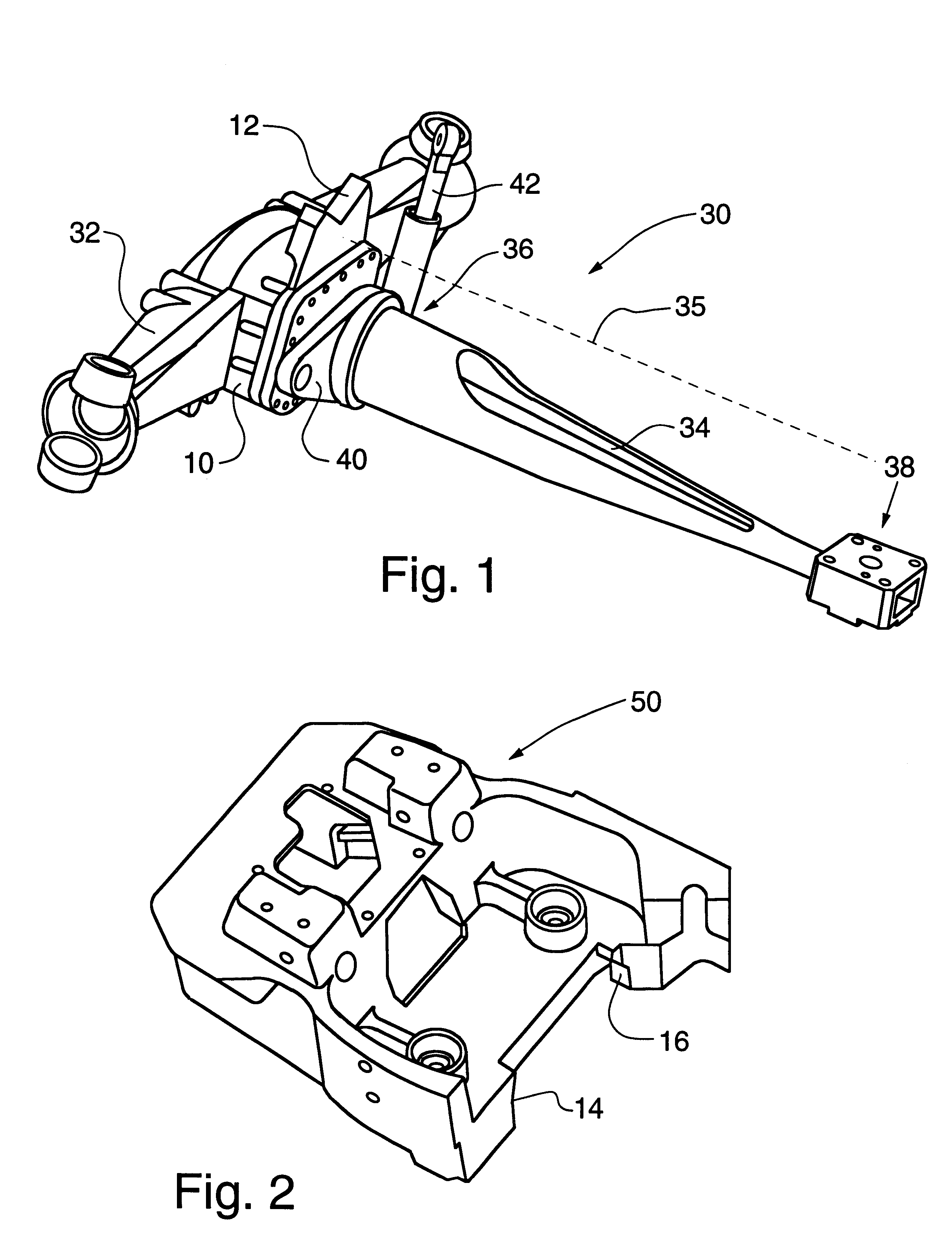
The axle 30 shown in FIG. 1, is T-shaped when viewed in plan with the front steerable wheels (not shown) of the tractor mounted on the ends of the cross bar 32 of the `T`. A drive shaft extends along the upright 34 of the `T` to a differential mechanism mounted within a housing 10 at the junction between the upright 34 and the cross bar 32 of the `T`.

The axle 30 is journaled at two locations 36 and 38 along the length of the upright 34 of the `T` so that it can rotate about the longitudinal axis 35 of the tractor thereby allowing the wheels to move up and down in relation to the tractor chassis. Conventionally, both of the support journals 36 and 38 of the front axle 30 are fixed in relation to the tractor chassis so that the front end of the axle cannot move up and down in relation to the chassis but can simply rotate about the vehicle longitudinal axis. In such an arrangement, it suffices to provide fixed bump stops to limit the rotation of the front axle relative to the body.

It h...


PUM


Abstract

An agricultural vehicle is described having a front axle mounted on a suspension in a manner that permits the front axle to move up and down in relation to the vehicle body and to pivot about the vehicle longitudinal axis so as to allow the wheels on the ends of the axle to move up and down independently. In the invention, a stop plate is provided on the housing of the axle that projects vertically upwards towards the vehicle body. Abutment surfaces are provided on the vehicle body that straddle the stop plate. The surfaces abut the side edges of the stop plate at the limit of the permitted range of rotation of the front axle about the vehicle longitudinal axis.

Description

BACKGROUND OF INVENTION1. Field of ArtThe present invention relates to an agricultural vehicle having a front axle mounted on a suspension in a manner that permits the front axle to move up and down in relation to the vehicle body and to pivot about the vehicle longitudinal axis so as to allow the wheels on the ends of the axle to move up and down independently. A tractor of this type is described in U.S. Pat. No. 6,216,812.2. Description of Prior ArtIn a vehicle in which the front axle can only pivot about a longitudinal axis of the vehicle and cannot move up and down in relation to the vehicle body, it is possible to limit the rotation of the front axle along the vehicle longitudinal axis by providing fixed stops on the vehicle body that collide with the top surface of the housing of the axle at the limits of its permitted range of movement. Such suspension stops cannot however be used when the axle can move up and down as they would allow excessive pivoting of the axle when the a...

Claims


Application Information

Patent Timeline
Patent Type & Authority Patents(United States)
IPC IPC(8): B60G9/02B60G7/04B60G7/00B60B35/00B60G9/00
CPCB60B35/163B60G7/04B60G9/02B60B2900/351B60G2200/32B60G2204/45B60G2300/082B60Y2200/221B60G9/003B60G9/027B60G2200/324B60G2200/34B60G2200/422B60G2204/423
Inventor PERTUSI, PIERLUIGIBARNARD, ERIC
Owner BLUE LEAF I P INC
Learn More