Shock-resistant electronic circuit assembly

a technology of electronic circuits and components, applied in the direction of casings/cabinets/drawers, electric fuzes, electric apparatus casings/cabinets/drawers, etc., can solve the problem that the detonator is vulnerable to lesser external forces

Inactive Publication Date:
View PDF71 Cites 45 Cited by
  • Summary
  • Abstract
  • Description
  • Claims
  • Application Information

AI Technical Summary

Problems solved by technology

The use of a plastic casing and the absence of an encapsulation about the delay circuit indicates that the disclosed detonator is vulnerable to lesser external forces than could be withstood by a conventional detonator having a metal housing.

Method used


Image

  • Shock-resistant electronic circuit assembly
  • Shock-resistant electronic circuit assembly
  • Shock-resistant electronic circuit assembly

Examples


Embodiment Construction

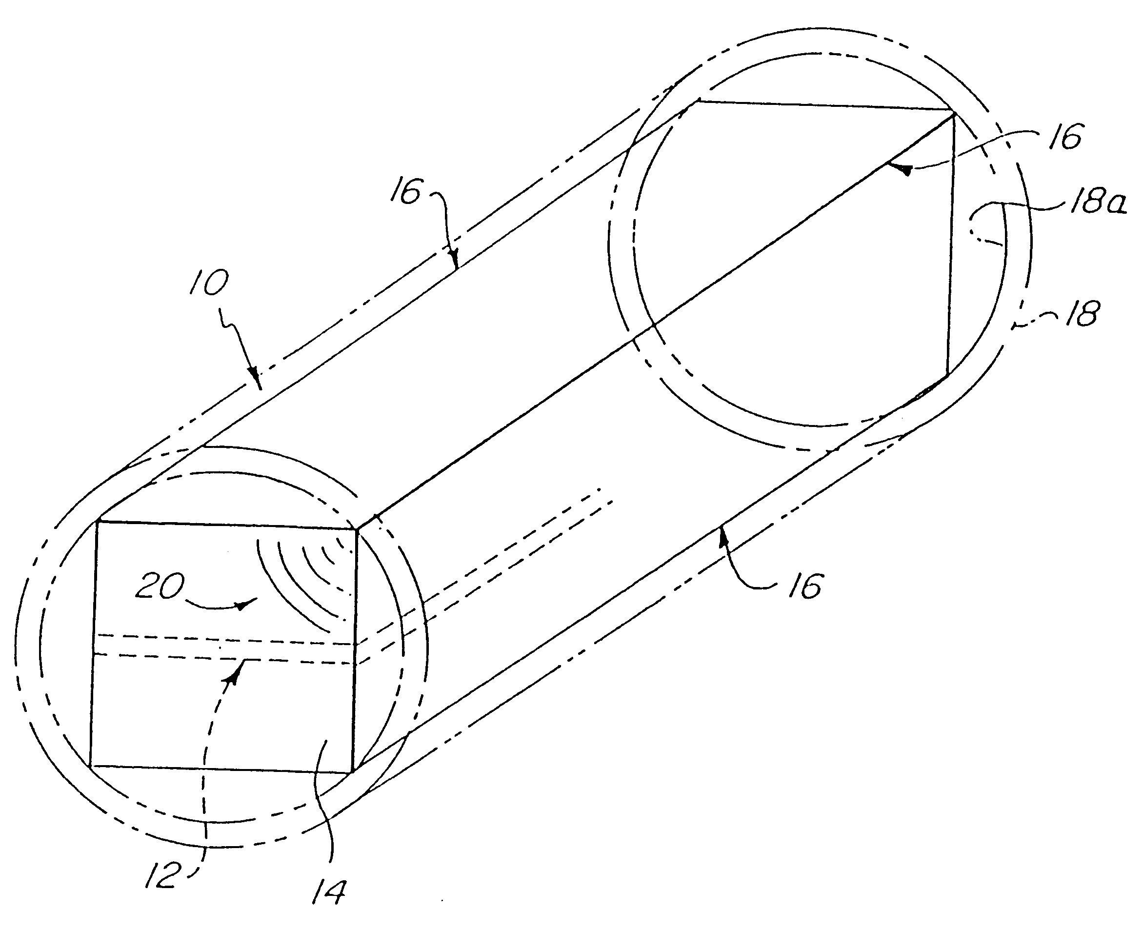
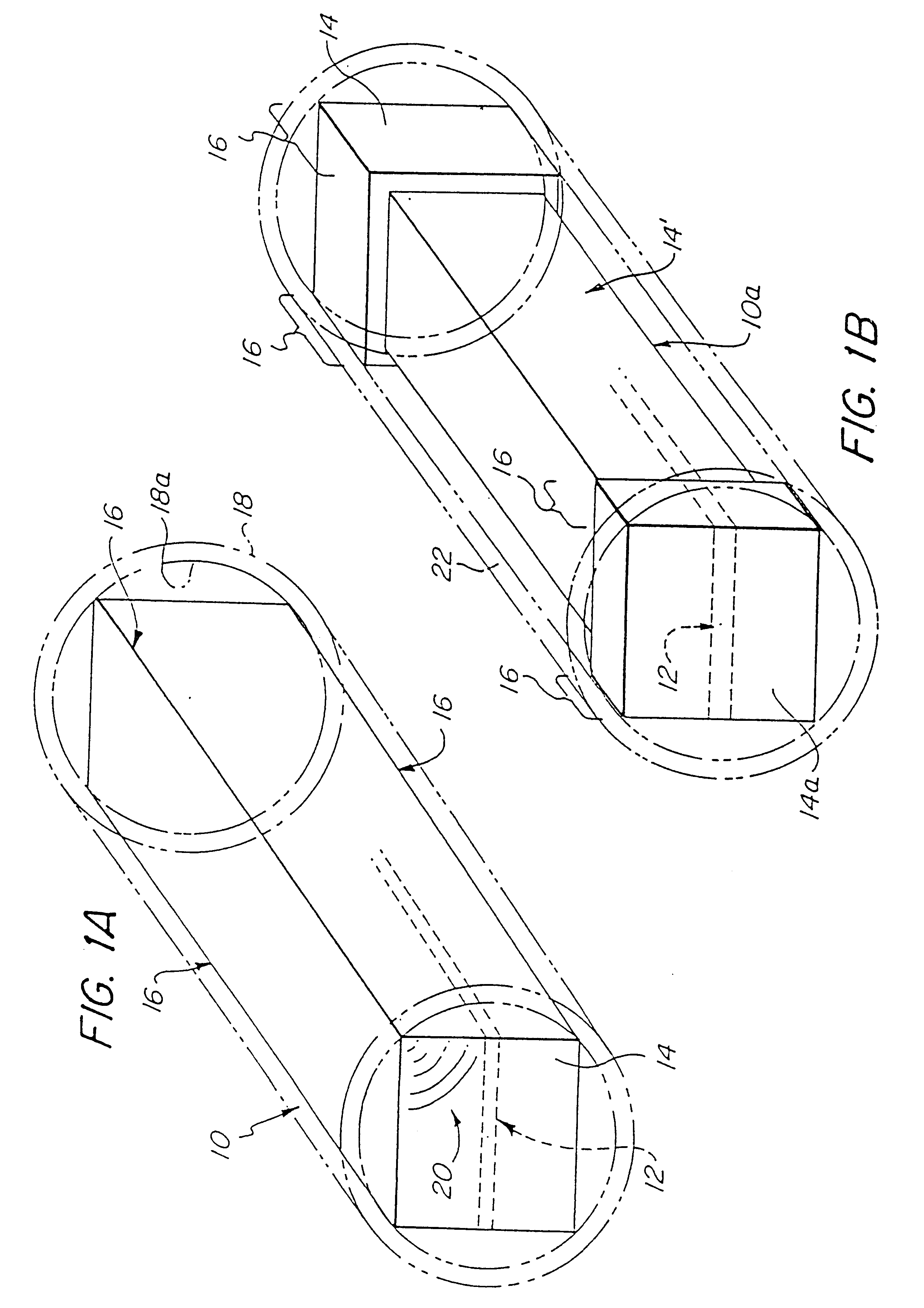
The present invention relates to protective encapsulations for electronic circuits to be disposed in rigid surrounding enclosures such as sleeves or shells. According to the present invention, part or all of an encapsulation may be configured as an integral structure molded about the circuit prior to positioning the circuit in the enclosure. Preferably, the encapsulation encases the circuit to protect the circuit from environmental damage, leaving external access only for input / output leads, e.g., for programming, testing and using the circuit. Thus, the preferred encapsulation protects the circuit elements from airborne contaminants at all times. It also protects the circuit after it is in the enclosure by attenuating shock waves received by the enclosure that might otherwise cause stress that causes damage to the circuit particularly, it is believed, at junctions between circuit structures and interfaces of materials of differing densities. The encapsulation also protects the circ...


PUM


Abstract

A shock-resistant electronic circuit assembly (10) is provided in which an electronic circuit is encased in an encapsulation (14) that engages a surrounding enclosure (18) in shock-dispersing contact therewith. The encapsulation may have a plurality of edges (16, 16a, 16b), fins (24) or bosses (70) that bear against the enclosure. The encapsulation may include a shock-absorbing material (14f) disposed against the enclosure to protect the circuit against vibrations and a structural support material such as a casing (14e) to protect the circuit against stress. The circuit assembly (10) may be part of a sheathed initiator assembly (55) that includes a transfer member (58) for converting shock wave energy into electrical energy for the electronic circuit, and the released energy may be converted into a detonation initiation signal. Assembly (55) may be part of a detonator (100) that receives a non-electric initiation signal and detonates following the delay determined by the electronic circuit. The detonator housing (112) or an optional sleeve (22) provides an enclosure for the assembly (55). The circuit encapsulation may include one or more bushings such as O-rings (14g, 14g') disposed about the circuit casing (14e).

Description

1. Field of the InventionThis invention relates to encapsulated electronic circuits and, in particular, to shock-resistant electronic circuit assemblies that find use in blasting components.2. Related ArtElectronic timing circuits for firing detonators after a predetermined, electronically-controlled delay period are known. The delay period is measured from the receipt of an initiation signal that may provide power for the timing circuit. Thus, U.S. Pat. No. 5,133,257 to Jonsson, issued Jul. 28, 1992, discloses an ignition system comprising a piezoelectric transducer that can be disposed next to a detonating cord branch line. When the detonating cord detonates, a shock wave is imposed on the piezoelectric transducer which then produces an electrical pulse. The electrical energy from the transducer is stored in a capacitor which provides power for a timer. After a predetermined delay, the timer allows the remaining stored energy in the capacitor to fire an ignition head in the detona...

Claims


Application Information

Patent Timeline
Patent Type & Authority Patents(United States)
IPC IPC(8): F42C19/00F42B3/12F42B3/00H05K5/02F42C11/06F42C11/00
CPCF42B3/121F42C19/00H05K5/0204
Inventor MARSHALL, PAUL N.TSEKA, THOMAS C.WALSH, BRENDAN M.FRITZ, JAMES E.
Why Eureka
Try Eureka