Apparatus and method for measuring voltage standing wave ratio in antenna of base station

a technology of standing wave ratio and antenna, which is applied in the direction of resistance/reactance/impedence, transmission monitoring, instruments, etc., can solve the problems of poor effect of transmission outlet, difficult equipment to measure the vswr on the receiver's side, and substantial degradation of the quality and effectiveness of system equipmen

Inactive Publication Date: 2001-11-06
LG ERICSSON
View PDF4 Cites 37 Cited by
  • Summary
  • Abstract
  • Description
  • Claims
  • Application Information

AI Technical Summary

Problems solved by technology

In general, the large VSWR means that the transmission output at the base station doesn't radiate in the air, but returns to a transmission outlet of the system as much as the amount of mis-matching and has a bad effect on its transmission outlet.
Namely, the mismatching means that VSWR is so large that the quality and effectiveness of the system equipment is substantially degraded.
At this time, the equipment to measure the VSWR on the receiver's side was quite complicated because the oscillator with the PLL was widely used to generates signals.
In other words, in measuring VSWR according to the prior art, there has been a big problem that an exclusive VSWR equipment only for measuring the VSWR and exclusive oscillator with the PLL and the reception coupler separately manufactured to measure the VSWR of the reception terminal become larger.
Furthermore, when measuring the VSWR of the reception part, there has been a problem that noise caused by the PLL oscillator or mixer could affect the precision of measurement of the VSWR ratio.
Accordingly, the operation of the reception terminal had a problem that it had to be stopped until the VSWR measuring is finished, which caused the entire base station system to be held up by the end of the VSWR measurement.
In general, it is more difficult for a coupler with three coupling ports to match each port's function than a coupler with two coupling ports.
Also, there is a problem in that it is difficult to manufacture the system and its manufacturing cost rises.
Further, there is provided a problem that it is difficult to measure the accurate characteristic of the voltage standing wave ratio owing to an operation of the oscillator.

Method used


Image

  • Apparatus and method for measuring voltage standing wave ratio in antenna of base station
  • Apparatus and method for measuring voltage standing wave ratio in antenna of base station
  • Apparatus and method for measuring voltage standing wave ratio in antenna of base station

Examples


Embodiment Construction

Reference will now be made in detail to the preferred embodiments of the present invention, examples of which are illustrated in the accompanying drawings.

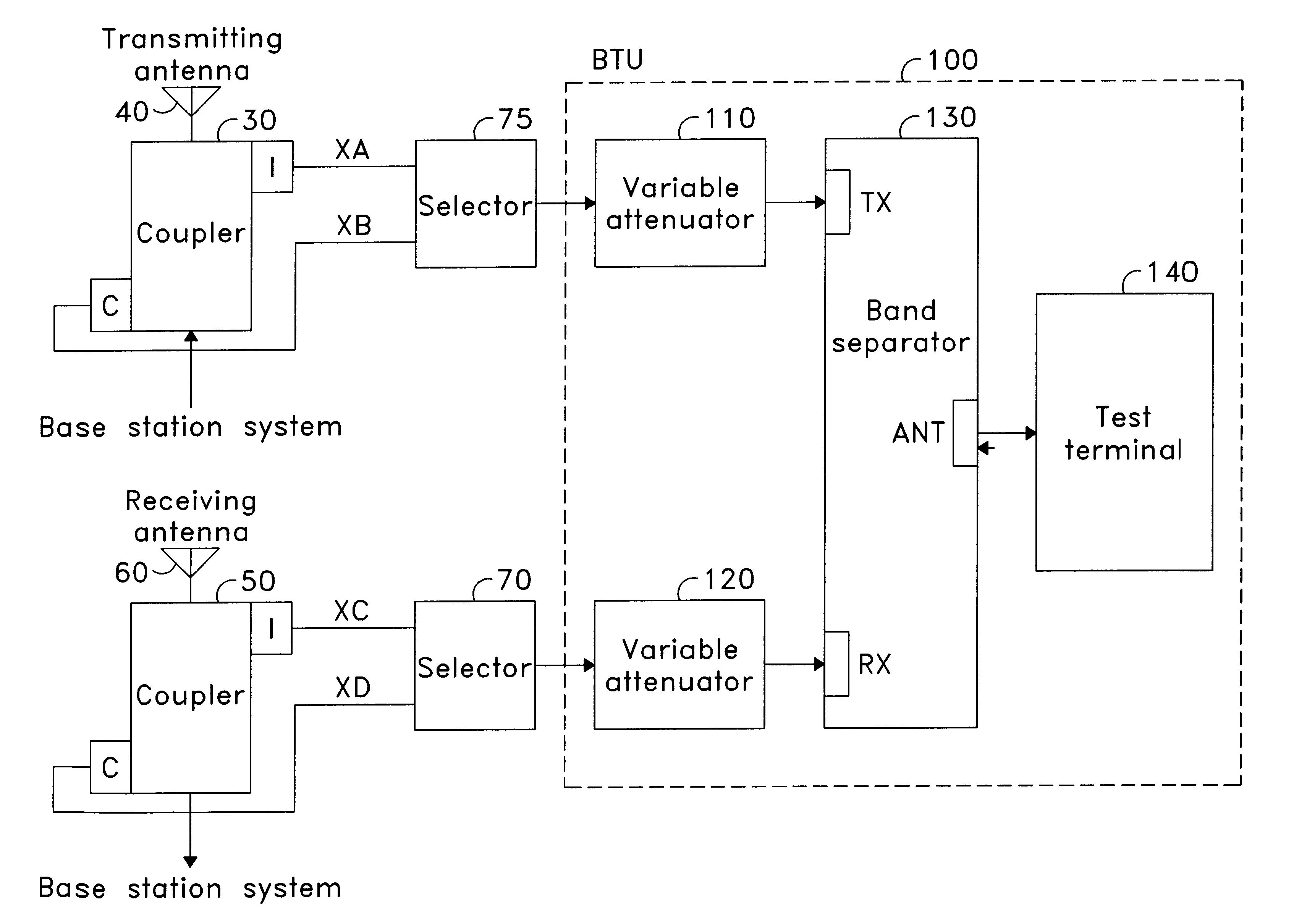
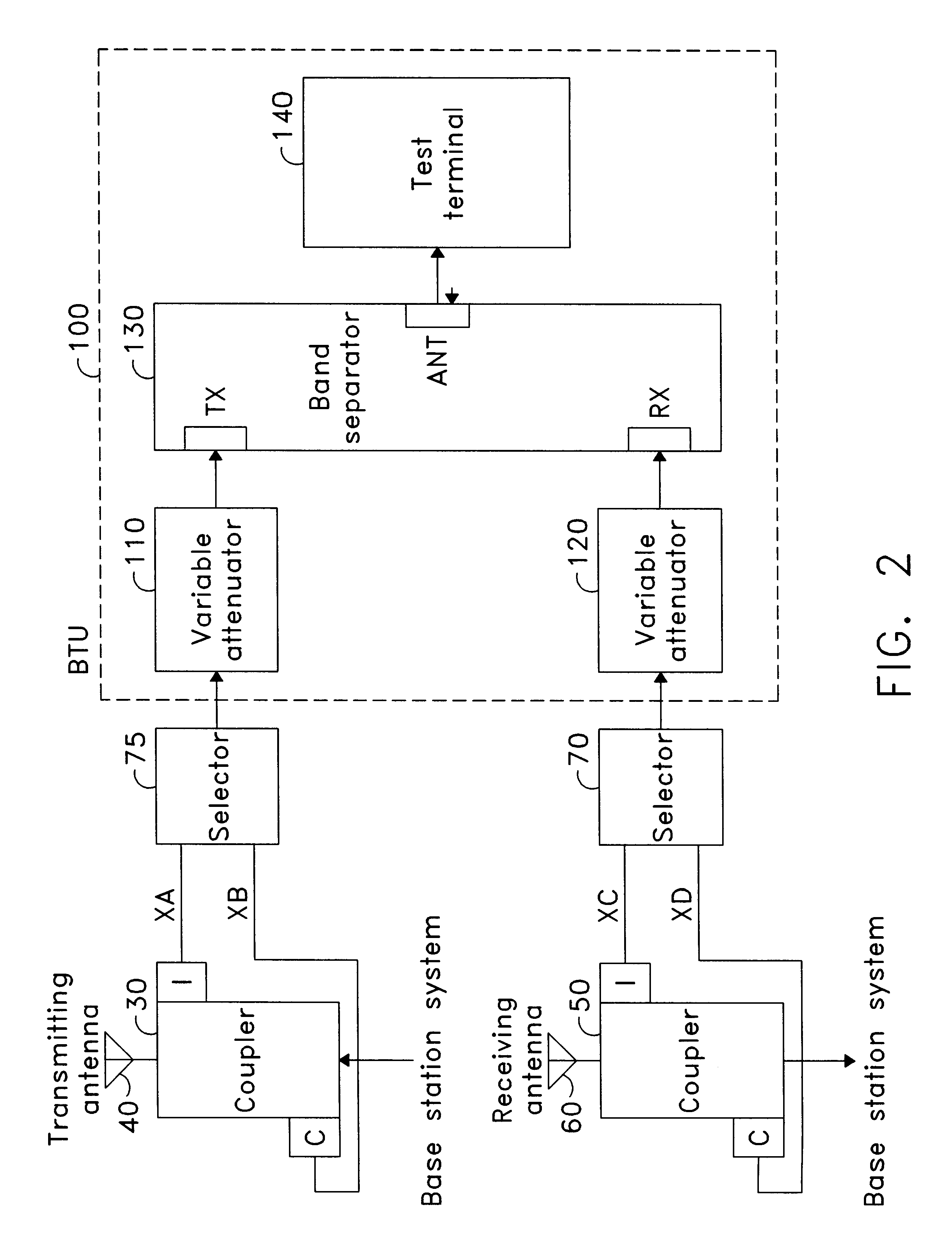
FIG. 2 is a construction view of a voltage standing wave ratio measurement apparatus of an antenna in a base station according to the present invention.

Referring to FIG. 2, there are provided a transmission coupler 30, a transmission selector 75, a base station test unit 100 having transmitting variable attenuator 110, band separator 130, test terminal 140, receiving variable attenuator 120, a reception selector 70, and a reception coupler 50. The transmission coupler 30 generates a direct path signal XB obtained by directly coupling an output signal by a coupling coefficient C in a coupling terminal, the output signal being applied from the base station. Also, the transmission coupler 30 generates a reflection signal XA coupled by the coupling coefficient C of an isolating terminal, the reflection signal being reflected from the ...


PUM


Abstract

An apparatus for measuring a voltage standing wave ratio of a base station. The apparatus comprises: a unit for measuring the voltage standing wave ratio of a transmitting terminal by coupling an input signal from the base station, and by comparing the difference of the coupled signal and a signal reflected from a transmitting antenna; and another unit for measuring the voltage standing wave ratio of a receiving terminal by comparing an input signal from a base-station test unit with the signal reflected from a receiving terminal.

Description

1. Field of the InventionThe present invention relates to an apparatus and a method for measuring a voltage standing wave ratio of an antenna of a base station, and more particularly to the apparatus and method for measuring the voltage standing wave ratio of a transferring terminal TX and a receiving terminal RX of the base station of a mobile communication, by using a base-station test unit for checking and testing the base station of the mobile communication.2. Discussion of Related ArtIn general, in the mobile communication system, it is an ideal that transmission output from the base station radiates in the air through a transmitting antenna. But the location of each base station, the surroundings and equipment installation conditions are different from each other, even though the same equipment is used, the efficiency in the transmission and reception of the base station is affected by the surroundings.Thus, in order to make the base station perform at an optimal state, the st...

Claims


Application Information

Patent Timeline
Patent Type & Authority Patents(United States)
IPC IPC(8): G01R27/06G01R27/04H04B17/00G01R31/00
CPCH04B17/103G01R27/06
Inventor KIM, YOUNG MINKIM, BO JONGKIM, DAE WON
Owner LG ERICSSON
Why Eureka
Try Eureka