Manufacturing method of a structure body

a manufacturing method and structure technology, applied in the field of manufacturing methods of structures, can solve the problems of high equipment cost, inconvenience such as face plate bends, and the inability to manufacture temporary fixing welding,

Inactive Publication Date: 2001-11-27
HITACHI LTD
View PDF9 Cites 36 Cited by
  • Summary
  • Abstract
  • Description
  • Claims
  • Application Information

AI Technical Summary

Problems solved by technology

For this reason, it is necessary to burden bearing members of the rotary tool to the large axial insertion force and this invites a high cost in the manufacture of the apparatus.
Further, when the member to be subjected to the joining is a hollow extruded frame member, the inconvenience such face plate bends by the insertion force causes.
Further, since the two members to be

Method used


Image

  • Manufacturing method of a structure body
  • Manufacturing method of a structure body
  • Manufacturing method of a structure body

Examples


Embodiment Construction

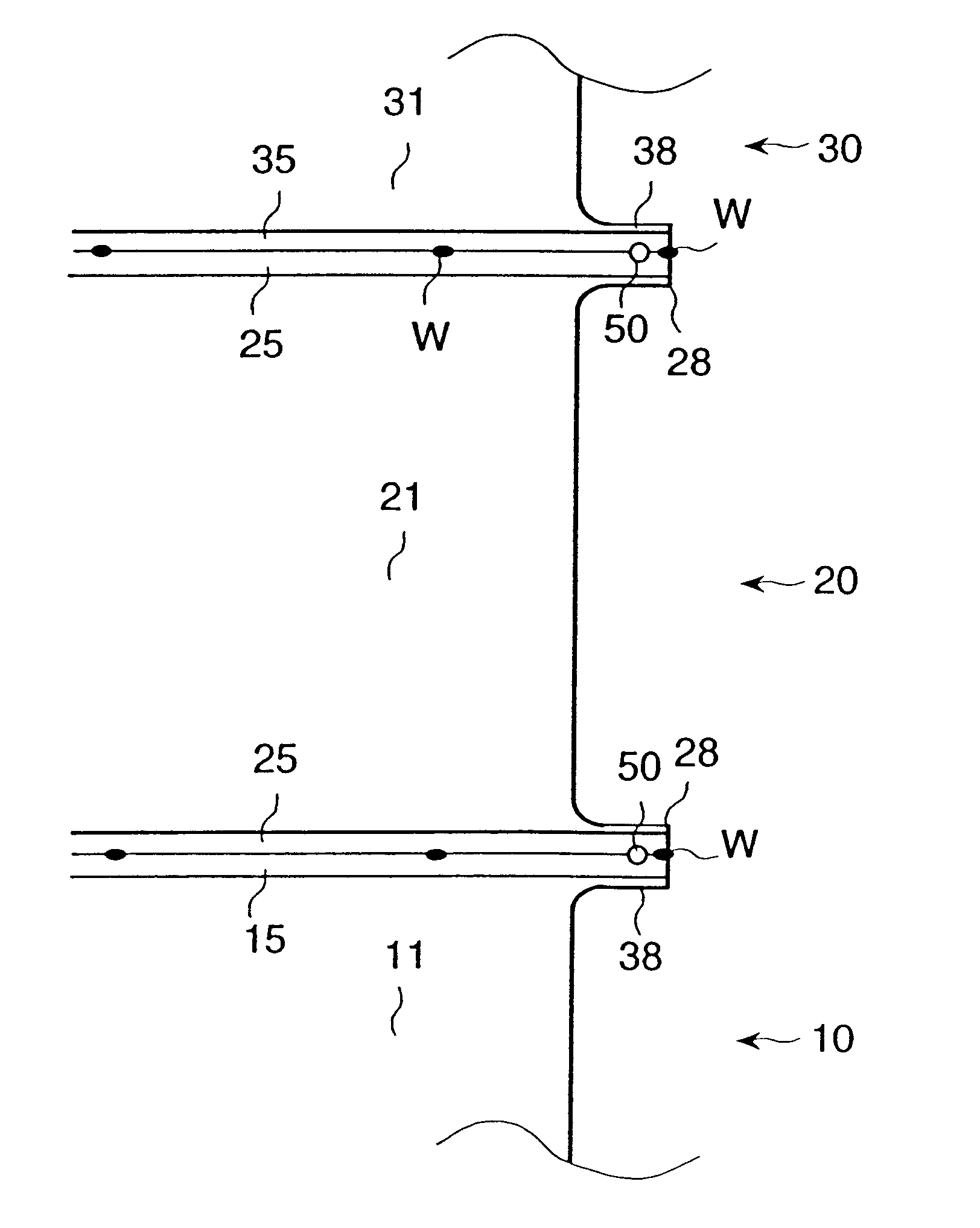
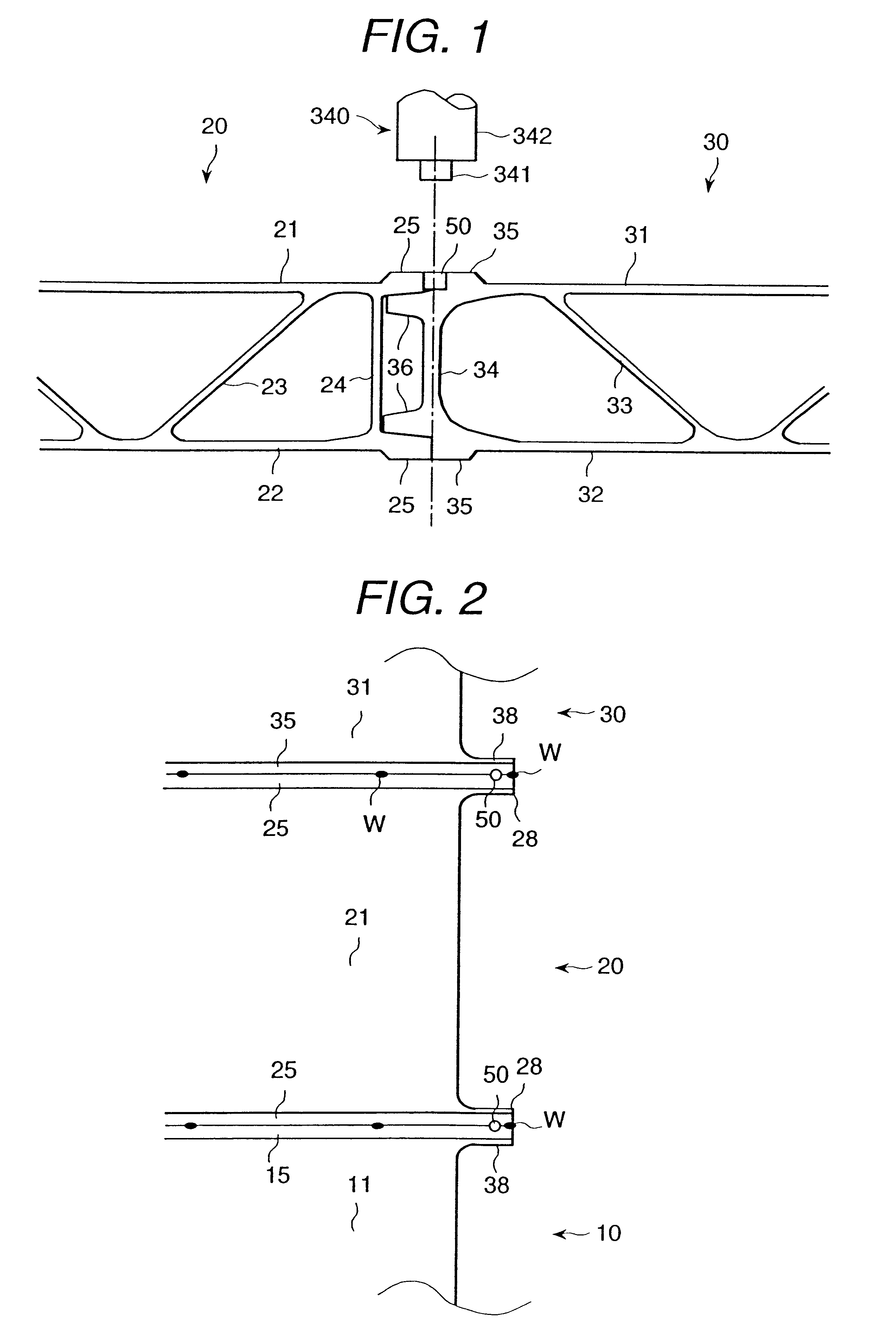
One embodiment according to the present invention will be explained referring to from FIG. 1 to FIG. 5. This is an example of a car vehicle as a structure body. FIG. 2 shows an end portion of a longitudinal direction of a side structure body 201.

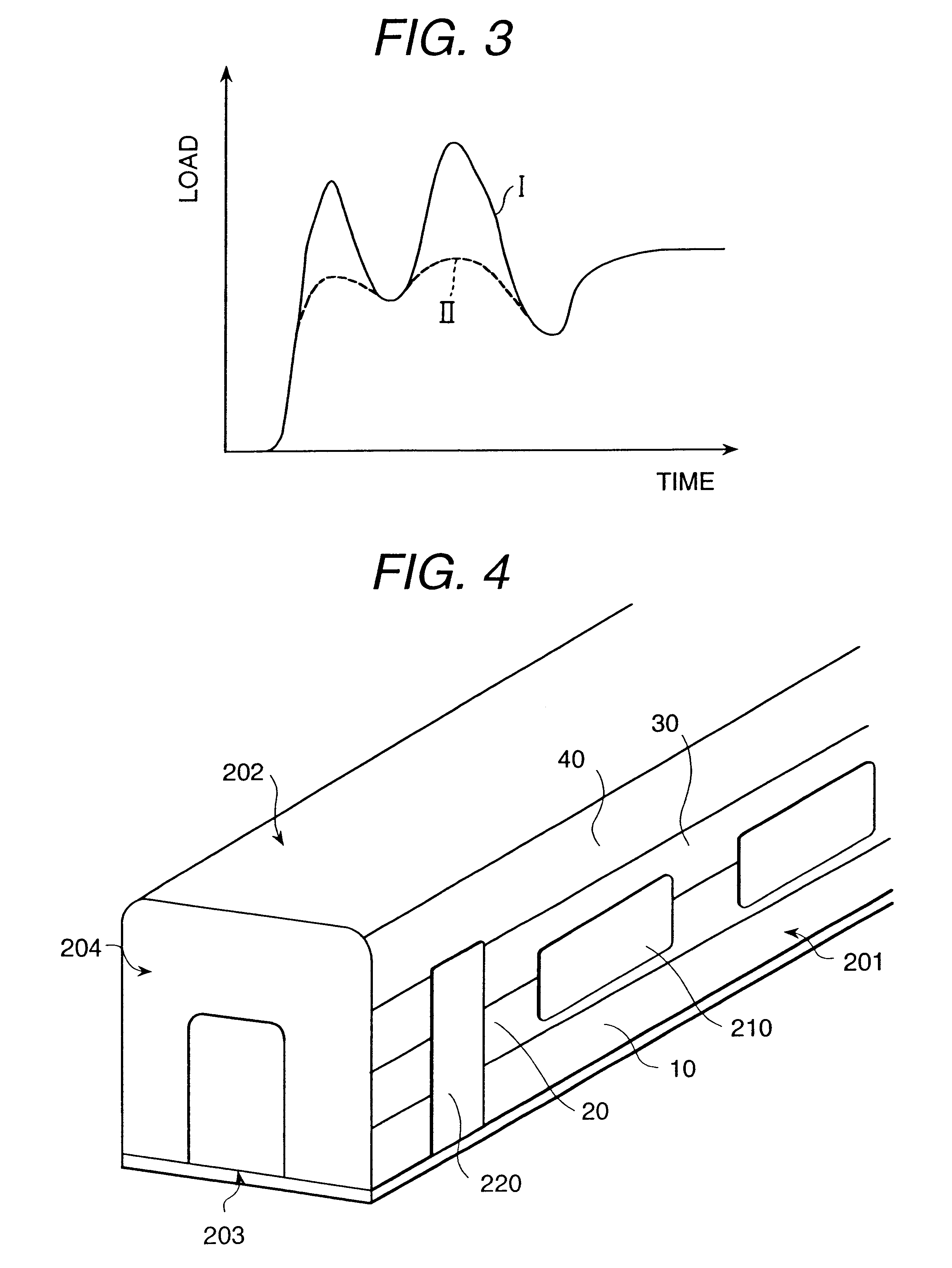
A car body is comprised of the side structure body 201, a roof structure body 202 for constituting a roof, a stand frame 203 for constituting a floor, and an end structure body 204 for constituting an end portion of a longitudinal direction. The side structure 201, the roof structure body 202, the stand frame 203 are constituted respectively by joining plural extruded frame members. A longitudinal direction of the extruded frame member is a longitudinal direction of the car body. The extruded frame member is an aluminum alloy made frame member.

The side structure body 201 is comprised of extruded frame members 10, 20, 30, 40. In the extruded frame members 20 and 30, a window 210 is formed. An inlet and outlet port 220 of the side structure bo...


PUM

PropertyMeasurementUnit
Forceaaaaaaaaaa
Diameteraaaaaaaaaa
Shapeaaaaaaaaaa

Abstract

When an insertion force of a rotary tool 340 has searched, it is made clearly that the force at the insertion initial time is large and when a friction stir joining is an ordinary operation time, the force becomes small. According, it is preferable to make small the insertion force at the insertion initial time. To members 20, 30 to be subjected to a joining at a position where the friction stir joining starts a hole 50 is opened, and this hole 50 after the rotary tool 340 has inserted, since a move of the rotary tool 340 is made to begin, a lowering of the insertion force can be attained.

Description

1. Technical FieldThe present invention relates to a manufacturing method of a structure body according to a friction stir joining method and, for example, the present invention is suitable for a joining of hollow extruded frame members.2. Prior ArtA friction stir joining method is a method in which by rotating a round rod (it is called as a rotary tool) which is inserted to a joining portion and moving it along to the joining line, the joining portion is exothermic heated and is softened and solid state fludized and a solid state joining is carried out. The rotary tool comprises a small diameter portion for inserting to the inserting portion and a large diameter portion which positions at an outside. The small diameter portion and the large diameter portion of the rotary tool have the same axis. A boundary between the small diameter portion and the large diameter portion of the rotary tool is inserted slightly to the joining portion. The rotary tool is inclined toward a rear portio...

Claims


Application Information

Patent Timeline
IPC IPC(8): B23K20/24B23K20/12F16B5/08F16B11/00
CPCB23K20/122B23K20/124B23K20/24B23K20/12
Inventor KAWASAKI, TAKESHIEZUMI, MASAKUNIINA, YOSHIHIKO
Owner HITACHI LTD
Why Eureka
Try Eureka