Magnet-actuated seat valve hydraulic brake systems of motor vehicles

Inactive Publication Date: 2001-11-27
ROBERT BOSCH GMBH
View PDF8 Cites 23 Cited by
  • Summary
  • Abstract
  • Description
  • Claims
  • Application Information

AI Technical Summary

Problems solved by technology

A disadvantage of this valve is that because of the deflection of the pressure fluid in the annular chamber near the valv

Method used


Image

  • Magnet-actuated seat valve hydraulic brake systems of motor vehicles
  • Magnet-actuated seat valve hydraulic brake systems of motor vehicles
  • Magnet-actuated seat valve hydraulic brake systems of motor vehicles

Examples


Embodiment Construction

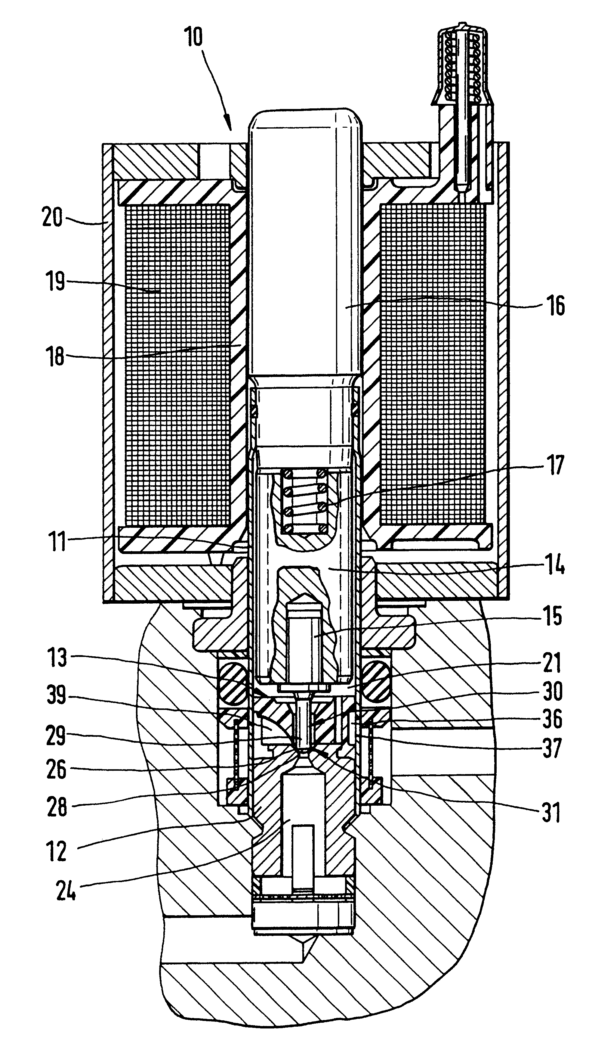
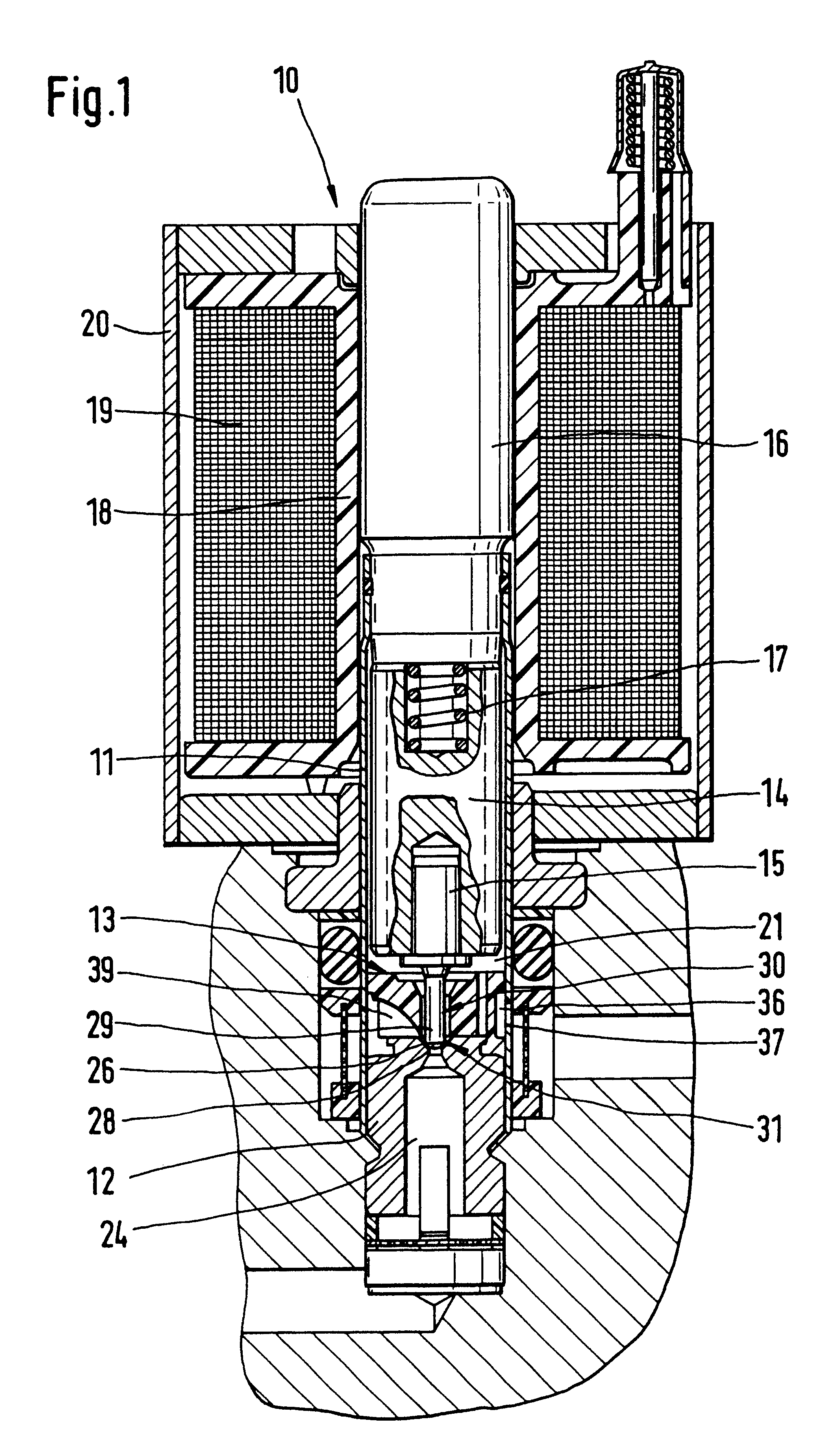
A hydraulic, magnet-actuated valve designated 10 in FIG. 1 and hereinafter called a magnet valve has essentially the following components in coaxial arrangement: a thin- walled, tubular valve housing 11 having an end portion of which a valve body 12 is disposed and secured in pressure-tight fashion in the valve housing. A guide body 13 for pressure fluid is received in the valve housing 11 and braced on a face end on the valve body 12. A magnet armature 14 is guided longitudinally movably in the valve housing 11 with a tappet 15 press-fitted into the armature on a side toward the guide body. A pole core 16 closes off the valve housing 11 on another end portion and is connected to the other end portion in pressure-tight fashion. A restoring spring 17 is disposed between the magnet armature 14 and the pole core 16. A coil 18 grasps the pole core 16 and the valve housing 11, with an electric winding 19; and a housing 20 that carries magnetic flux and surrounds the coil 18 and the windi...


PUM


Abstract

A tubular valve housing includes a guide body for pressure fluid that is disposed between a valve body having a hollow-conical valve seat and a chamber of the valve housing, in which actuating means of the valve are received in the chamber. The guide body is penetrated by a closing body of the valve which divides the chamber from an annular conduit. The annular conduit carries the pressure fluid and communicates with the valve seat and has circumferential outlet openings of the valve housing. The guide body is braced on the valve body, with a face end contacting the valve body, and has guide conduits, fitting over an outline of the valve seat, which on the outlet side discharge into the annular conduit. The face end of the closing body, which cooperates with the valve seat, is a spherical portion that makes a transition with sharp edges to the cylindrical shaft of the closing body. With the guide body, the stream of pressure fluid emerging from the valve seat is diverted into the annular conduit, so that flow instabilities are largely without any effect on the chamber of the valve. The valve can be used in brake systems of motor vehicles.

Description

PRIOR ARTThe invention is based on a hydraulic, magnet-actuated valve for hydraulic brake systems of motor vehicles.From German Patent Disclosure DE 40 31 885 A, which defines this generic type, a magnet-actuated hydraulic valve is known that has a hollow-conical valve seat of a seat valve, to which a closing body with a cylindrical shaft and a conical face end, whose conicity differs from that of the valve seat, is assigned. In the valve housing of this valve, with axial spacing from the valve seat, a guide body for pressure fluid is secured. The guide body is penetrated by the shaft of the closing body. Between the valve seat and the opposed end face of the guide body, there is an annular chamber for receiving pressure fluid that has emerged from the seat valve in the form of a hollow-closing body and, through the closing body shaft, on the actuating means of the valve.A valve is also known (DE 41 29 638 A) in which a hollow-cylindrical guide body is press-fitted into the valve ho...

Claims


Application Information

Patent Timeline
IPC IPC(8): B60T15/00B60T15/02B60T8/36F15B13/04F15B13/044F15B13/00F16K31/06
CPCB60T8/363B60T8/367B60T15/028F15B13/0405F15B13/044F16K13/00
Inventor HOFMANN, DIRKHOHL, GUENTHERAMBROSI, MASSIMOLAIER, CHRISTIAN
Owner ROBERT BOSCH GMBH
Why Eureka
Try Eureka