Method and apparatus for suppressing flow instabilities in an optical fiber draw system

a draw system and flow instability technology, applied in the field of fiber draw system, can solve the problems of inacceptable fiber diameter variation, increased operational complexity of collecting, cleaning and reusing helium from the draw furnace,

Active Publication Date: 2019-09-26
CORNING INC
View PDF0 Cites 1 Cited by
  • Summary
  • Abstract
  • Description
  • Claims
  • Application Information

AI Technical Summary

Benefits of technology

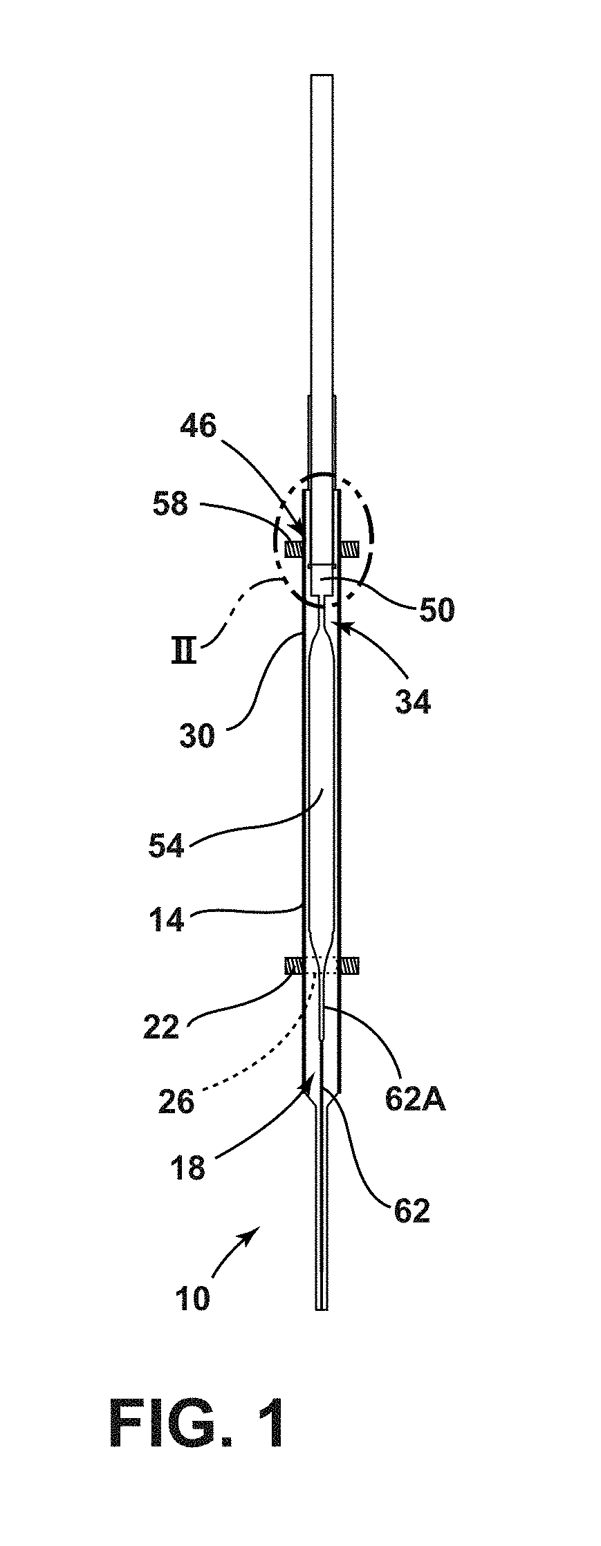
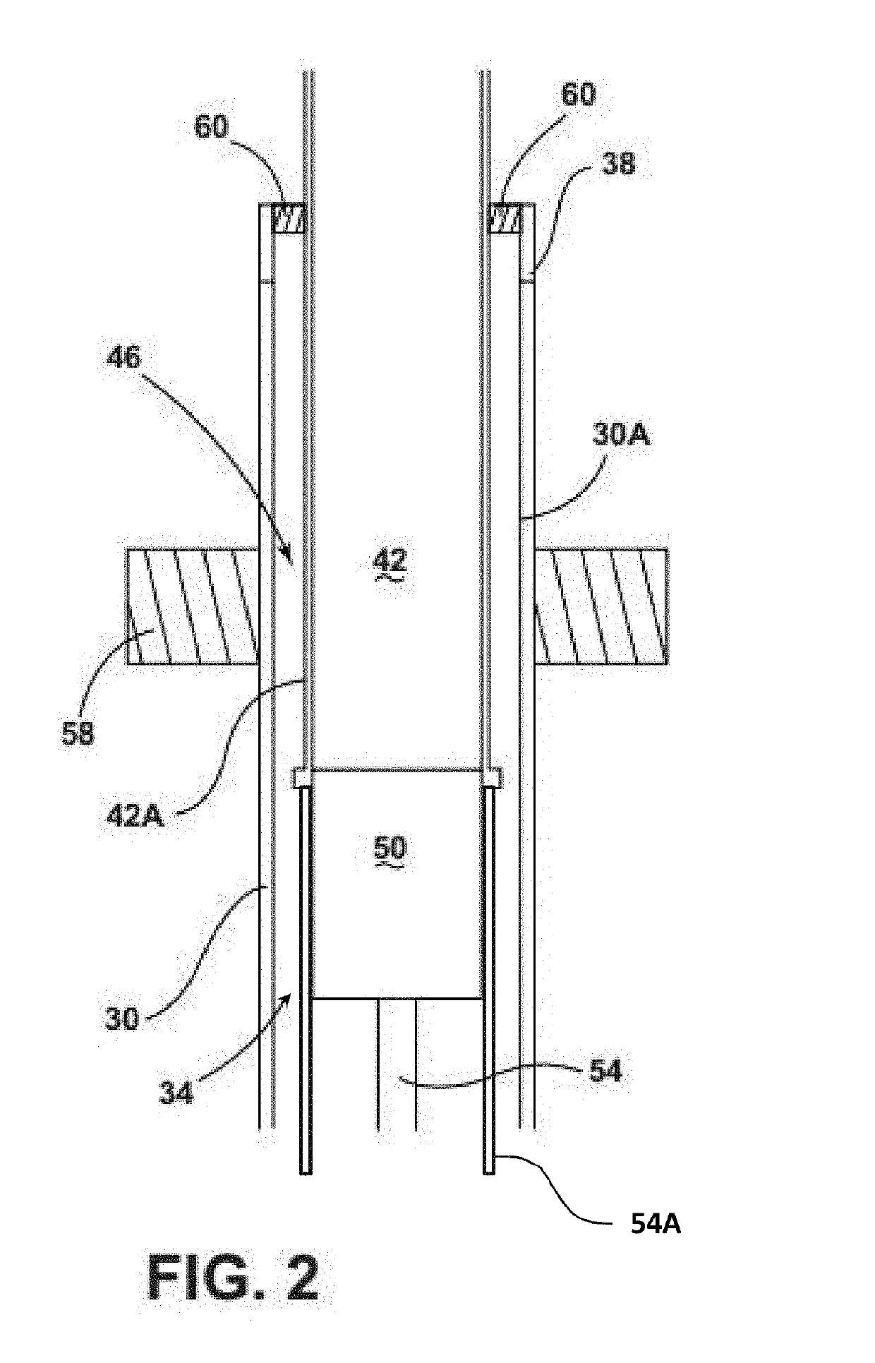
[0018]According to a tenth aspect, the furnace system of aspect 8 is provided, wherein the length of the gap is about 3 cm or less as measured from the outer surface of the downfeed handle to the inner surface of the upper muffle extension.
[0019]According to an eleventh aspect, the furnace system of aspect 8 is provided, wherein the length of the gap is about 2.

Problems solved by technology

Recycling of helium from the fiber draw furnace increases operational complexity to collect, clean, and reuse the draw furnace helium.
Use of other i

Method used


Image

  • Method and apparatus for suppressing flow instabilities in an optical fiber draw system
  • Method and apparatus for suppressing flow instabilities in an optical fiber draw system
  • Method and apparatus for suppressing flow instabilities in an optical fiber draw system

Examples


examples

[0070]Referring now to FIGS. 4A through 7D, depicted are computational fluid dynamic (CFD) simulations of gas flow and heat transfer within a furnace assembly (e.g., the furnace system 10). The CFD simulations were validated using historical observations based on current production configurations to confirm their validity.

[0071]Referring now to FIGS. 4A-4D, depicted is a CFD model of a first comparative example.

[0072]In Comparative Example 1, a temperature variation occurs along an axial dimension of the furnace 80 (e.g., similar to furnace system 10) with a heating zone (e.g., similar to the hot zone 26) of the furnace 80 having a temperature of about 2100° C. and a temperature of an upper portion 84 (e.g., similar to the handle cavity 34 and / or gap 46) being much lower at about 200° C. A handle 88 (e.g., similar to the downfeed handle 42) has an outside diameter of about 7.62 cm and an upper muffle 92 (e.g., similar to the upper muffle extension 30) has a larger inner diameter suc...


PUM

PropertyMeasurementUnit
Temperatureaaaaaaaaaa

Abstract

A furnace system includes a muffle defining a furnace cavity. A lower heater is coupled to the muffle and is configured to create a hot zone within the furnace cavity having a temperature of about 1900° C. or greater. An upper muffle extension is positioned above the muffle and defines a handle cavity. A downfeed handle is positioned within the handle cavity such that a gap is defined between an outer surface of the downfeed handle and an inner surface of the upper muffle extension. An upper heater is thermally coupled to the upper muffle extension and configured to heat the gap. A gas screen is positioned in the upper muffle extension and is configured to inject a process gas into the handle cavity.

Description

[0001]This application claims the benefit of priority to Dutch Patent Application No. 2020854, filed on 1 May 2018, which claims the benefit of priority to U.S. Provisional Application Ser. No. 62 / 646,584 filed on Mar. 22, 2018, the content of which is relied upon and incorporated herein by reference in its entirety.FIELD OF THE DISCLOSURE[0002]The present disclosure generally relates to a fiber draw system, and more specifically, to a method and system for suppressing flow instabilities in the fiber draw system.BACKGROUND[0003]Helium gas is used in various stages of conventional fiber manufacturing processes. For some manufacturing processes, a large fraction of the consumption of helium is in the fiber draw furnace where active purging of the furnace with an inert gas is required to prevent air entrainment and oxidation of the hot components. Helium is a nonrenewable resource recovered as a byproduct from natural gas wells. As the price of helium is projected to increase in the fu...

Claims


Application Information

Patent Timeline
IPC IPC(8): C03B37/029
CPCC03B2205/91C03B37/029C03B37/0253C03B2205/60C03B2205/61C03B2205/62C03B2205/80
Inventor ANDERSON, ERLING RICHARDHOFFMANN, TAMMY MJEWELL, JOHN MICHAELKLADIAS, NIKOLAOS PANTELISMOORE, ROBERT CLARK
Owner CORNING INC
Why Eureka
Try Eureka