Fuel cell system using external heat sources for maintaining internal temperature

a fuel cell and internal temperature technology, applied in battery/fuel cell control arrangement, electrochemical generators, electric propulsion mounting, etc., can solve the problems of wasting fuel, destroying parts of the system, and requiring the time to change over from a non-productive cold start mode to an operating mode productive,

Active Publication Date: 2007-05-31
APTIV TECH LTD
View PDF14 Cites 32 Cited by
  • Summary
  • Abstract
  • Description
  • Claims
  • Application Information

AI Technical Summary

Problems solved by technology

A first recognized problem in operation of prior art fuel cell systems is the time required to change over from a non-productive cold start mode to an operating mode productive of electricity.
Drawbacks of this procedure are that it is wasteful of fuel, and it creates undesirably large thermal stresses on elements of the reformer and stack which can damage or destroy parts of the system.
A second recognized problem is how to maintain a prior art fuel cell system at a standby readiness condition (that is, at near-operating temperature) such that the system may be changed over to operating mode in a very short period of time.
Again, this procedure is wasteful of fuel.
In small scale systems, however, a self-sustaining usage profile may not be economic when compared to purchasing lower cost grid electricity most of the time, and additional or premium insulation may not be acceptable in terms of packaging (size of the unit) and cost.

Method used


Image

  • Fuel cell system using external heat sources for maintaining internal temperature
  • Fuel cell system using external heat sources for maintaining internal temperature
  • Fuel cell system using external heat sources for maintaining internal temperature

Examples


Embodiment Construction

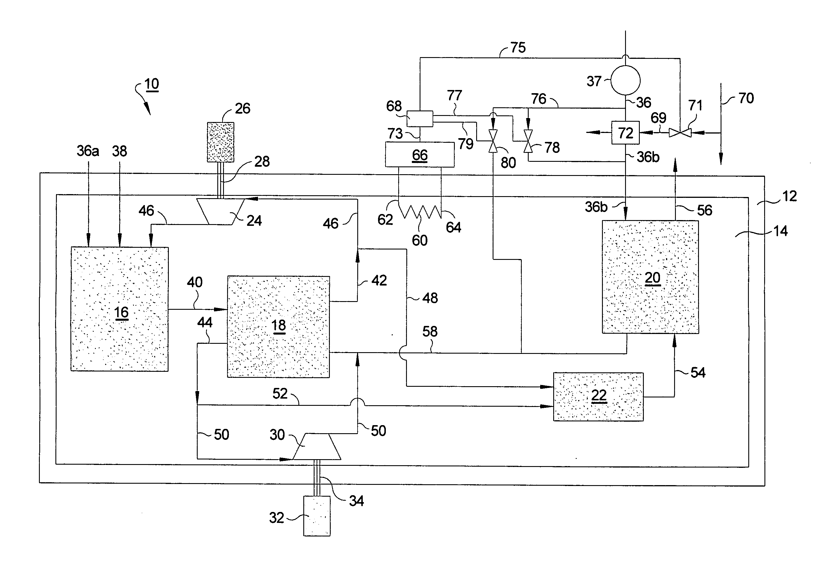
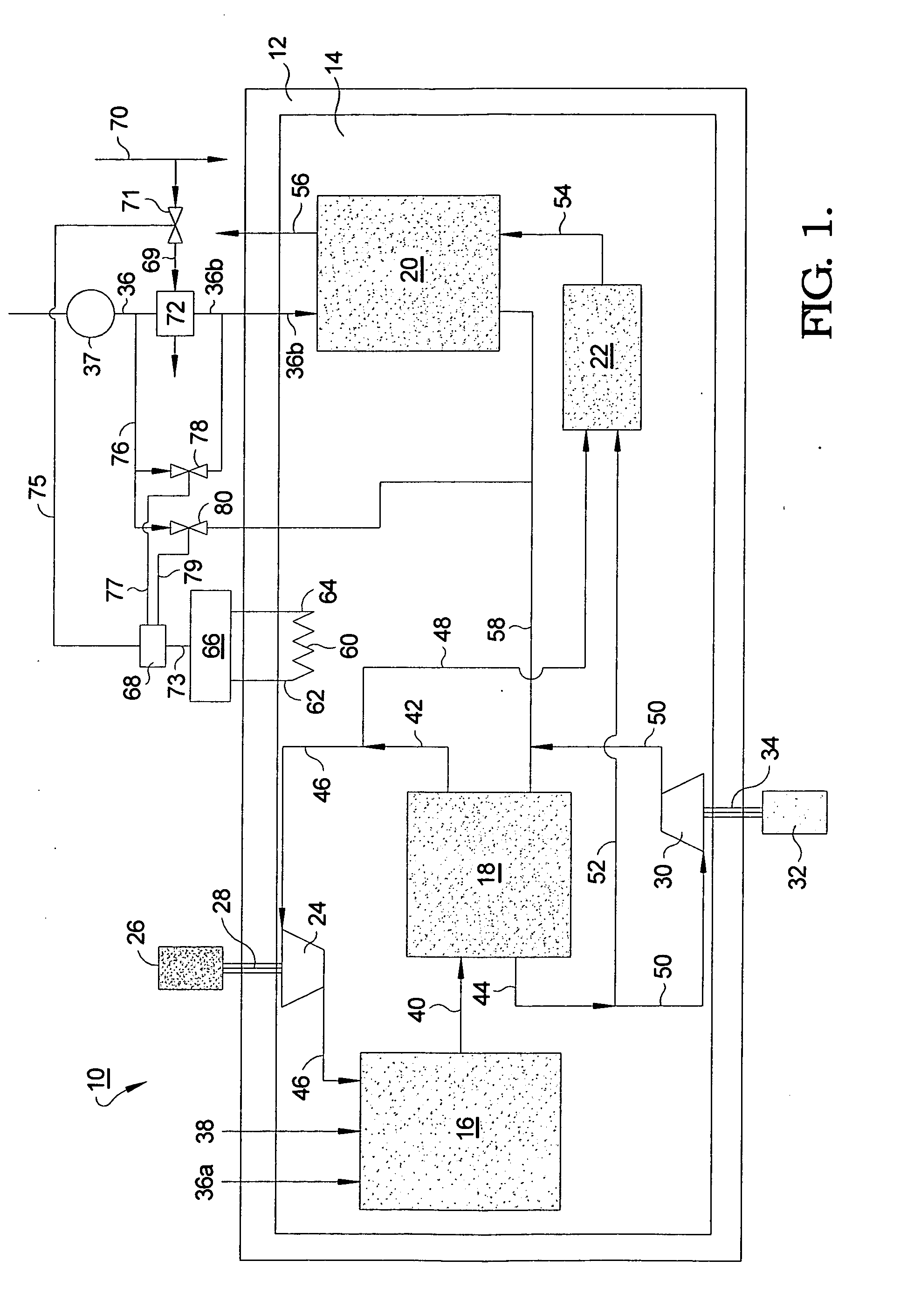
[0015] The present invention is directed to methods and apparatus for electric resistance heating of space and elements within the “hot zone” enclosure of a solid oxide fuel cell system, preferably in combination with means for using “waste” heat from other sources, to assist in warm-up from a cold start and / or to maintain a stand-by temperature of reformer and fuel cell elements within the system and / or to maintain optimum operating temperatures within the system during periods of very low electrical and thermal demand on the system.

[0016] Referring to FIG. 1, a solid oxide fuel cell system 10 in accordance with the invention comprises an insulated enclosure 12 defining therewithin a heated space 14, known colloquially in the art as “the hot zone”. A catalytic hydrocarbon fuel reformer 16, SOFC stack 18, cathode air heat exchanger 20, and anode tailgas combustor 22 are disposed within enclosure 12 for operation at elevated temperatures as is well known in the SOFC prior art. Furth...


PUM


Abstract

A solid oxide fuel cell system including electric resistance elements for heating of space and components within the “hot zone” enclosure of the system, preferably in combination with means for using “waste” heat from other sources, to assist in warm-up from a cold start and / or to maintain a stand-by temperature of reformer and fuel cell elements within the system and / or to maintain optimum operating temperatures within the system during periods of very low electrical demand on the system. A method is included for using off-peak grid electricity, battery-stored onboard electricity, or vehicle-generated electricity to energize the resistance heaters, as well as utilizing gaseous waste heat sources such as vehicle exhaust gas to complement the resistance heating.

Description

RELATIONSHIP TO OTHER APPLICATIONS AND PATENTS [0001] The present application is a Continuation-In-Part of pending U.S. patent application Ser. No. 11 / 370,285, filed Mar. 8, 2006, which claims the benefit of Provisional Application Ser. No. 60 / 668,166, filed Apr. 4, 2005.TECHNICAL FIELD [0002] The present invention relates to solid oxide fuel cell (SOFC) systems; more particularly, to means for providing heat to the stacks and / or reformer of a solid oxide fuel cell system; and most particularly, to a solid oxide fuel cell system having resistive electric heating elements disposed therein for warming up and / or maintaining the temperatures of components of the system. BACKGROUND OF THE INVENTION [0003] A typical prior art solid oxide fuel cell system is fueled by a hydrogen-containing reformate fuel derived from catalytic reforming of either liquid or gaseous hydrocarbons such as gasoline or methane. Thus, such a fuel cell system must have a source of supply, which may be onboard stor...

Claims


Application Information

Patent Timeline
Patent Type & Authority Applications(United States)
IPC IPC(8): B60K1/00
CPCB60L11/1881B60L11/1885B60L11/1892B60L11/1894H01M8/04037H01M8/04074H01M8/04268H01M8/2475H01M16/006H01M2008/1293H01M2250/20H01M2250/402H01M2250/405H01M2250/407H02J3/387H02J7/1415H02J2001/004Y02B90/12Y02E60/563Y02T10/7005Y02T90/32Y02T90/34Y02E60/50Y02E60/525Y04S10/126Y02E60/721Y02B90/16B60L58/30B60L58/31B60L58/33B60L58/34H02J2300/30H02J2300/10H02J3/381Y02B90/10Y02T90/40Y02T10/70Y02E60/10Y02E60/00
Inventor GRIEVE, MALCOLM JAMES
Owner APTIV TECH LTD
Why Eureka
Try Eureka