Electrical connector for cardiac devices

a technology of electrical connectors and cardiac devices, applied in the field of temporary medical electrical leads, can solve problems such as undesirable trauma to surgical patients

Inactive Publication Date: 2001-11-27
ETHICON INC
View PDF11 Cites 41 Cited by
  • Summary
  • Abstract
  • Description
  • Claims
  • Application Information

AI Technical Summary

Problems solved by technology

Unfortunately, the pad is sutured to the atrial wall and this causes trauma.
All of these describe suturing or other mechanical means to attach the electrodes to tissue, consequently leading to undesirable trauma to the surgical patient.

Method used


Image

  • Electrical connector for cardiac devices
  • Electrical connector for cardiac devices
  • Electrical connector for cardiac devices

Examples


Embodiment Construction

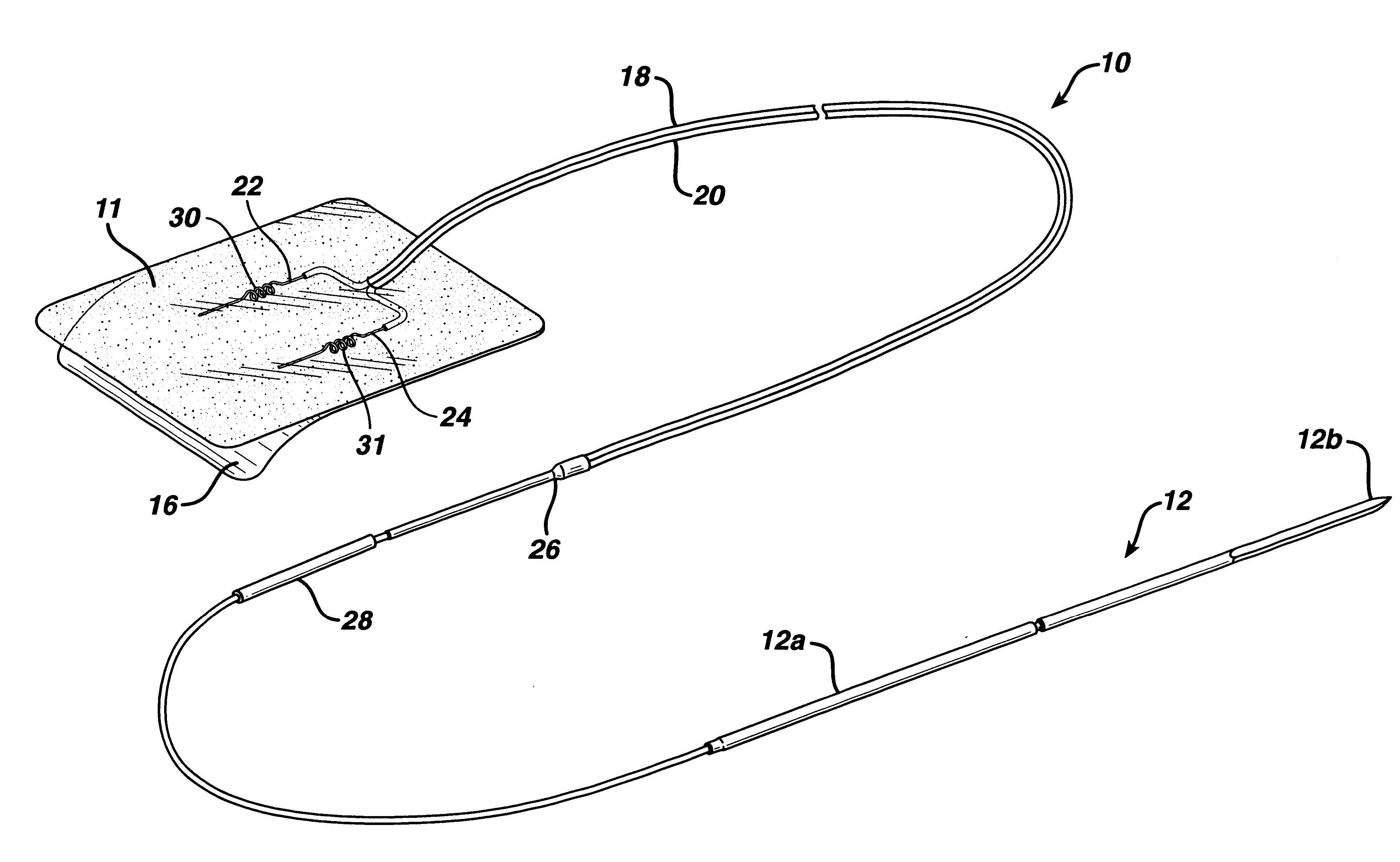
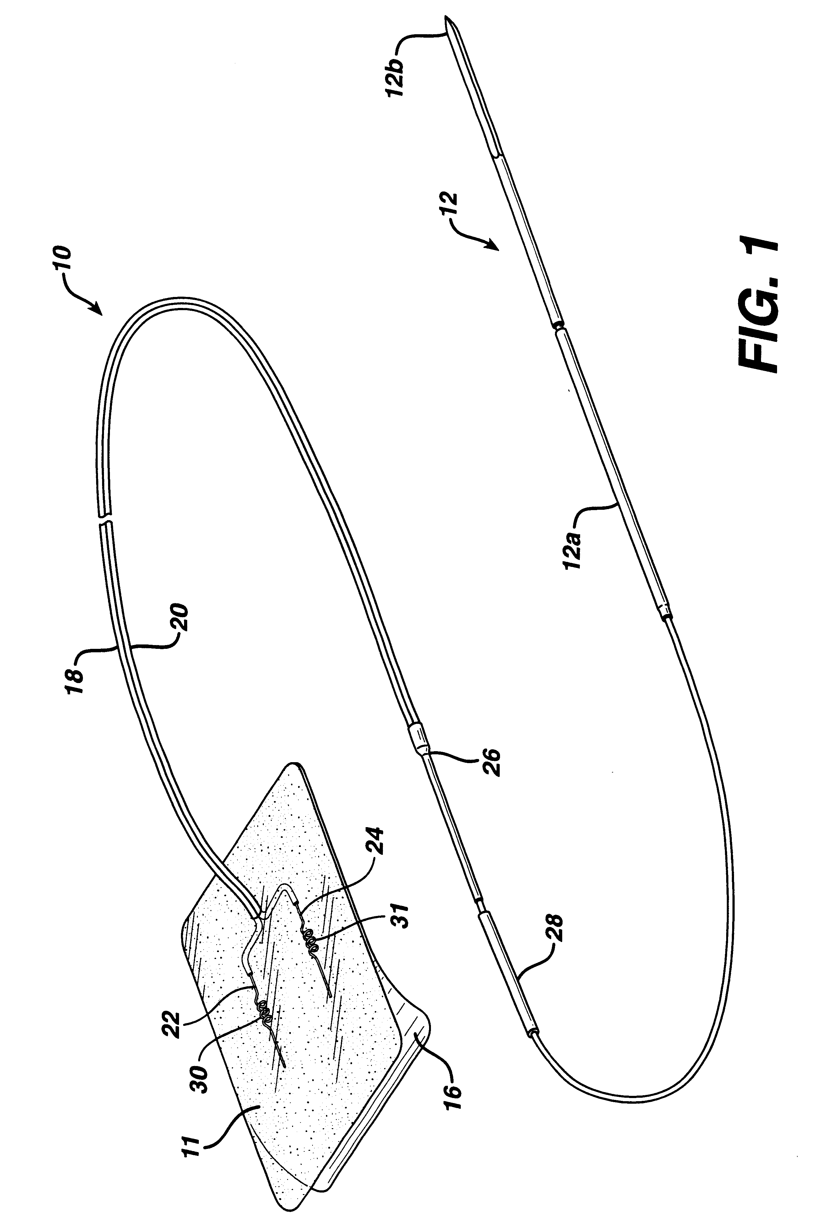
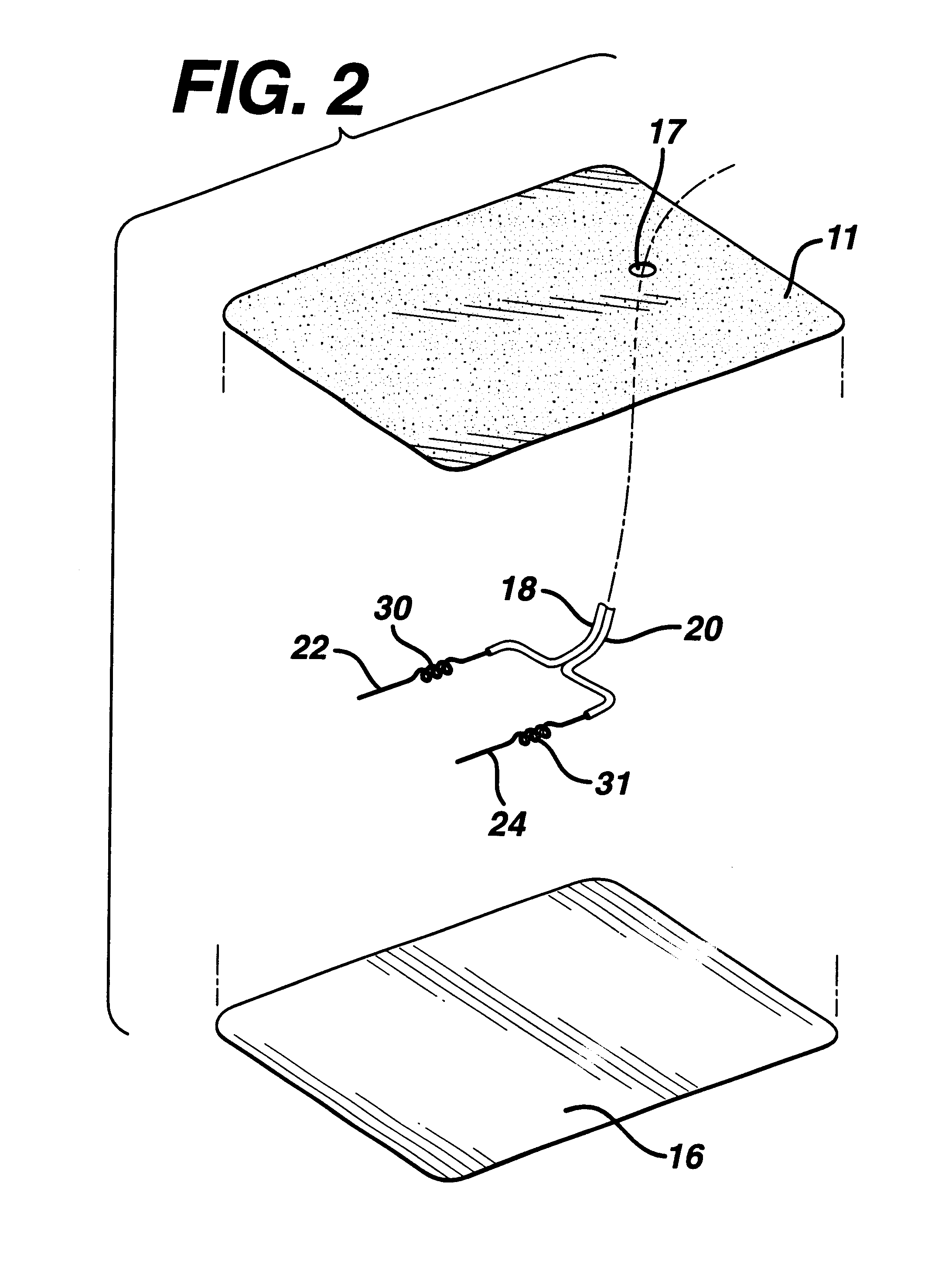
Bipolar temporary pacing wires were constructed in accordance with the preferred embodiment of this invention and as illustrated in the figures. The wires were applied to wet pig hearts. The patches used for affixing the electrodes to the heart were composed of poly (p-dioxanone) polymer films coated with pressure sensitive medical grade RTV silicone adhesive. Each patch was about two square inches in size. 7 mg / in.sq. of adhesive was applied from the adhesive tube directly onto the tissue-contacting surface of each film. The first and second electrodes of the pacing wire were then affixed to the tissue-contacting surface of the polymeric film. Alternatively, any pressure sensitive adhesive could have been pre-applied to the film and subsequently covered by a release paper such as silicone paper.

A Chatillon Tensile Tester (crosshead speed=12 in / min with force gauge DFSI-50) was clamped onto a free portion of the proximal end of the pacing wire. The pacing wire was then removed. Resu...


PUM


Abstract

An electrical connector for a cardiac device is disclosed. The connector has a wire and an electrode at the distal end of the wire. The wire is attached to a patch, and the patch is coated with an adhesive film for adhering the patch to tissue. The preferred connector is a bipolar temporary cardiac pacing wire. The use of an adhesive film eliminates or reduces the need for suturing the patch to tissue, thus avoiding or significantly reducing tissue trauma associated with suturing.

Description

The present invention relates to electrical connections for cardiac devices and, more particularly, to temporary cardiac pacing wires that are adapted for use with apparatus that generate electrical signals suitable for stimulating, pacing, sensing, monitoring or defibrillating the heart.Devices to stimulate or regulate cardiac function have been known and used for decades. They involve a power source (pacemaker) and one or more surgical electrodes to attach the source to the heart. They are generally of two types.Implantable pacers are intended for long-term use and, as the name suggests, are entirely implanted in the body. The other type is intended for temporary use. The temporary pacemaker is located outside the body and is connected to the heart by a surgical electrode called a "temporary pacing wire." Although surgical electrodes are used for preparing electrocardiograms and other applications, for the sake of brevity, the description that follows is focused on temporary pacin...

Claims


Application Information

Patent Timeline
Patent Type & Authority Patents(United States)
IPC IPC(8): A61N1/05A61B5/0478A61B5/0408
CPCA61N1/0587
Inventor SHCHERVINSKY, SEMYONSAFERSTEIN, LOWELLILORI, ALEX B.MAURER, ROBERT E.
Owner ETHICON INC
Why Eureka
Try Eureka