Automatic hand-supportable laser bar code symbol scanner and method of reading bar code symbols using the same

a laser bar code symbol and scanner technology, applied in the direction of instruments, dynamo-electric converter control, sensing by electromagnetic radiation, etc., can solve the problems of affecting the user's experience, the user's most fatiguing requirement, and the user's inability to pull the trigger to initiate scanning of bar code symbols,

Inactive Publication Date: 2001-12-11
METROLOGIC INSTR
View PDF45 Cites 19 Cited by
  • Summary
  • Abstract
  • Description
  • Claims
  • Application Information

AI Technical Summary

Problems solved by technology

While such prior art devices are capable of successful bar code symbol reading, they nevertheless suffer from several significant shortcomings and drawbacks.
The requirement is most fatiguing on the user when large numbers of bar code symbols are to be read.
Also, in certain symbol reading applications, such as warehouse inventory, pulling the trigger to initiate scanning of bar code symbols may be extremely difficult for the user due to the physical location of the objects bearing the bar code symbols.
While capable of automatically initiating scanning of bar code symbols, such prior art devices and incorporated techniques nevertheless also suffer from significant shortcomings and drawbacks.
While the triggerless bar code symbol reader proposed in U.S. Pat. No. 4,639,606 possesses three modes of operation, this prior art bar code symbol reader nevertheless suffers from several significant shortcomings and drawbacks.
In particular, this prior art bar code symbol reader requires continuous use of a pulsed laser beam to determine the presence of an object within the scan field, which, in hand-held portable battery power devices, undesirably drains limited power reserves, especially in extended time duration bar code reading applications.
Consequently, when using this prior art bar code symbol reader, the user has no ability to manually control its operation in order to selectively read a bar code symbol one or more times as desired.
While this prior art scanning technique permits detection of bar code symbols within the scan field in order that the power of

Method used


Image

  • Automatic hand-supportable laser bar code symbol scanner and method of reading bar code symbols using the same
  • Automatic hand-supportable laser bar code symbol scanner and method of reading bar code symbols using the same
  • Automatic hand-supportable laser bar code symbol scanner and method of reading bar code symbols using the same

Examples


Embodiment Construction

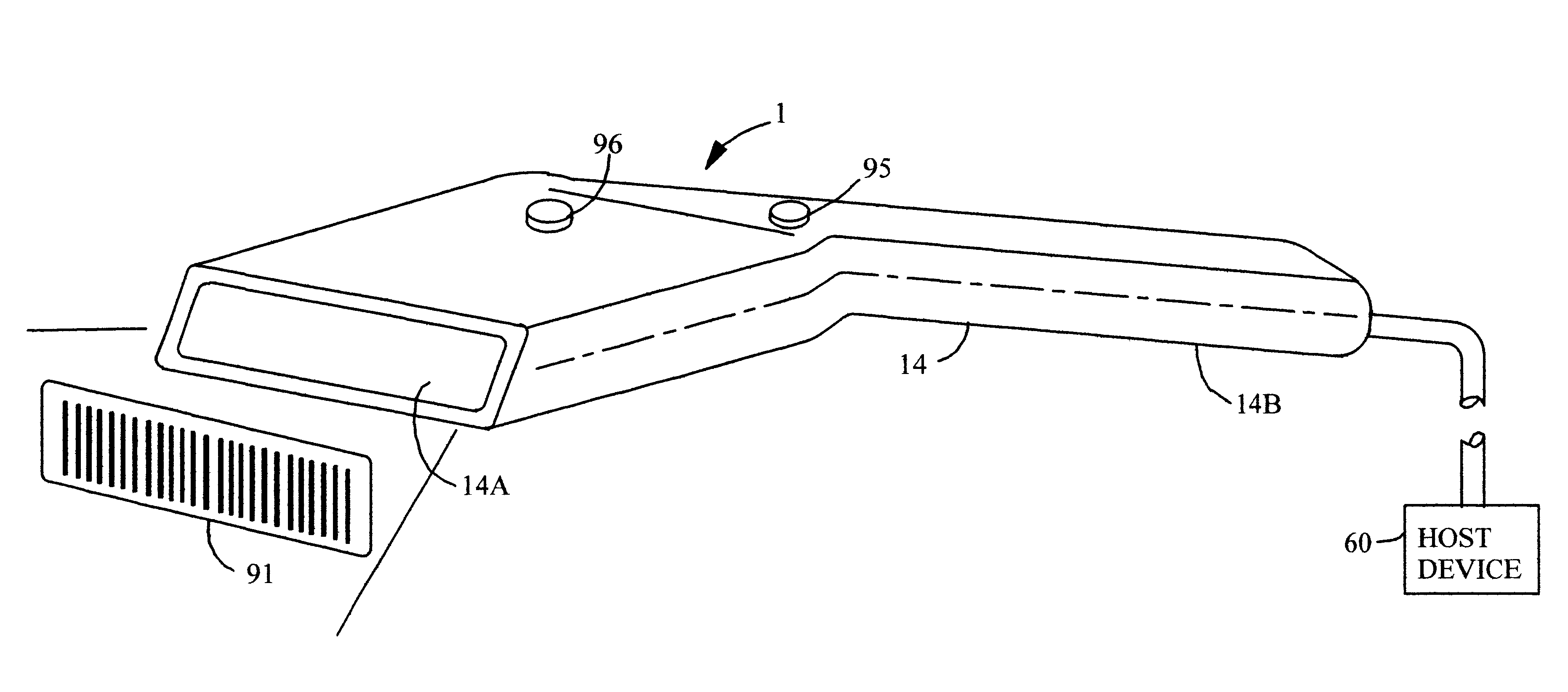
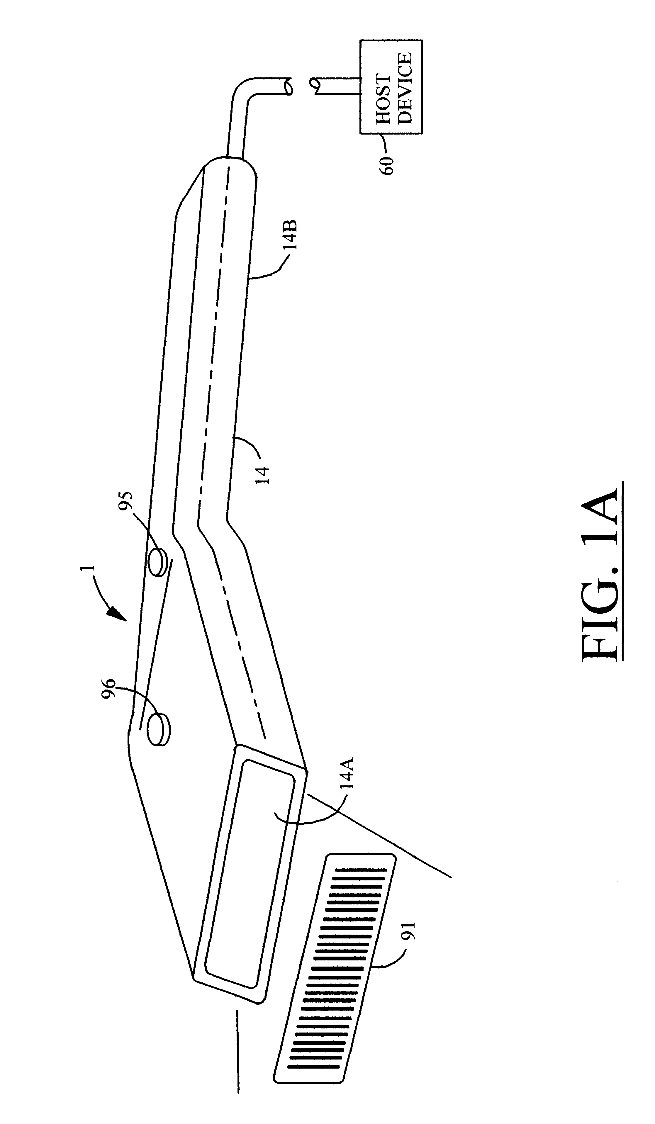
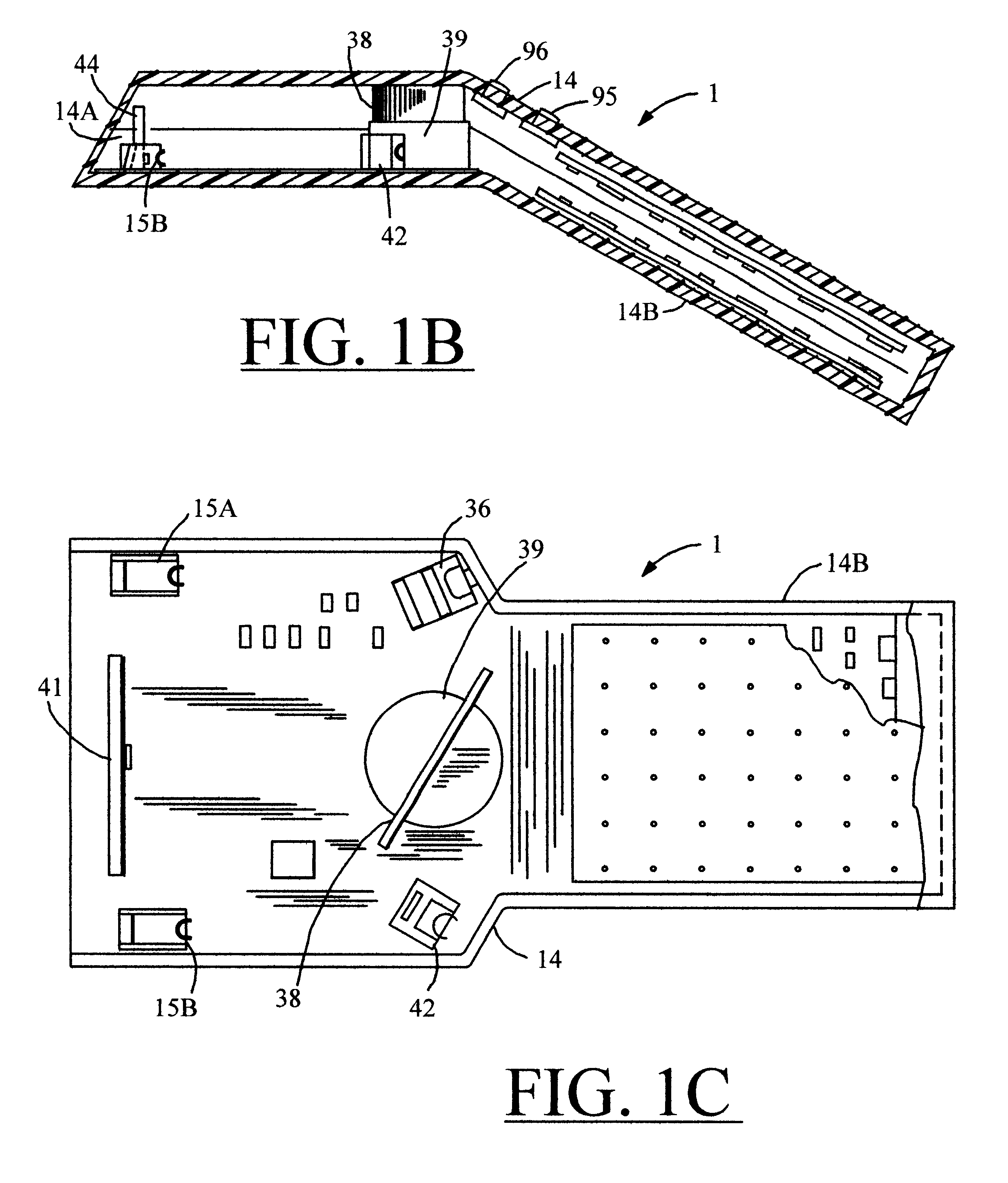
The automatic bar code symbol reading system 1 of the present invention, is generally illustrated in FIGS. 1 through 10.

As shown in FIG. 2, bar code symbol reading system 1 comprises a number of system components, namely, system activation means 2, scanning means 3, photoreceiving means 4, bar code presence detection means 5, analog-to-digital (A / D) conversion means 6, symbol decoding means 7, data format conversion means 8, symbol character data storage means 9, and data transmission means 10. As illustrated, these system components are embedded within a programmable control system having a unique architecture which provides a great degree of versatility in system capability and operation, as well as power conservation. The structure, function and advantages of this control system architecture will be described in great detail hereinafter.

The control system of the present invention comprises essentially three major components, namely first control means (C.sub.1) 11, second control...


PUM


Abstract

An automatic bar code symbol reading system comprising components for carrying out object detection, scanning, photoreceiving, A/D conversion, bar code presence detection, symbol decoding, data format conversion, data storage and data transmission functions. In general, the automatic bar code symbol reading device includes a manually actuatable read-repeat switch and control system having a plurality of control centers that control the operation of the system components in accordance with preselected system control operations. Each of the control centers are responsive to control activation signals generated by certain of the system components upon the occurrence of predefined conditions. Certain of the control centers are capable overriding other control centers to provide diverse control capabilities which facilitates execution of intelligent operations and power conservation, during bar code symbol reading. In combination, control system and read-repeat switch enable the device to automatically read a previously read bar code symbol once again, or retransmit or restore symbol character data of a previously read bar code symbol, each time the read-repeat switch is depressed during the system control process of the present invention. This simple procedure can be repeated time and time again to read, in a user-controllable fashion, the same bar code symbol any number of times.

Description

1. Field of the InventionThe present invention relates generally to automatic code symbol reading (i.e., recognition) systems, and more particularly to an automatic code symbol reading device having a control system which permits multiple modes of fully automated operation while conserving power and providing versatility in its method of use.2. Brief Description of the Prior ArtHitherto, a number of techniques have been proposed for reading bar code symbols using hand-held devices. Despite variety amongst prior art bar code symbol reading devices, the various techniques incorporated into prior art devices can be classified into two principally distinct classes, namely, manually operated or triggered bar code symbol reading devices, and automatic bar code symbol reading devices.Representative of prior art manually operated bar code symbol reading devices are U.S. Pat. No. 4,387,297 to Swartz, et al., U.S. Pat. No. 4,575,625 to Knowles, and U.S. Pat. No. 4,845,349 to Cherry. While suc...

Claims


Application Information

Patent Timeline
IPC IPC(8): G06K7/10G06K7/14G06K17/00
CPCG06K7/10564G06K7/10584G06K7/10594G06K7/10603G06K7/10693G06K7/10702G06K7/10792G06K7/10801G06K7/10851G06K7/10871G06K7/10881G06K7/10891G06K7/109G06K7/14G06K7/1443G06K17/0022G06K2207/1012G06K2207/1016G06K2207/1017G06K2207/1018
Inventor WILZ, SR., DAVID M.ROCKSTEIN, GEORGE B.KNOWLES, CARL H.
Owner METROLOGIC INSTR
Why Eureka
Try Eureka