
Apparatus and method for detecting signals of space-time coding based on transmission diversity

a technology of space-time coding and antenna, applied in diversity/multi-antenna systems, amplitude demodulation, multiplex communication, etc., can solve problems such as difficult to accurately estimate, impede effective and reliable data transmission, and inability to use space diversity methods for mobile stations

Inactive Publication Date: 2002-08-01
KT CORP
View PDF4 Cites 23 Cited by
  • Summary
  • Abstract
  • Description
  • Claims
  • Application Information

AI Technical Summary

Problems solved by technology

The multi-path fading occurring in most mobile communication channels serves as the main cause of impeding effective and reliable data transmission.
However, such space diversity method is not practical for a mobile station because of its cost, size, power consumption, etc.
However, such reception of the space-time encoded symbol only provides the channel estimate of one sample for one slot despite the weighted average, so that the fast fading channel not only makes it difficult to precisely estimate the channel gain varying in the slot interval, but also the use of the inexact channel estimate may further distort all the data of a slot in the environment of great noises and interferences with a number of mobile stations.
Moreover, the combination of the outputs of all the decoders without considering the reception level results in the combination of the decoders' outputs lower than the threshold value, and degrade the performance of the receiving system of the space-time encoded symbol due to the reduction of the signal to noise power ratio of the detected symbol.

Method used


Image

  • Apparatus and method for detecting signals of space-time coding based on transmission diversity
  • Apparatus and method for detecting signals of space-time coding based on transmission diversity
  • Apparatus and method for detecting signals of space-time coding based on transmission diversity

Examples


Embodiment Construction

[0035] Hereinafter, preferred embodiments of the present invention will be described in detail with reference to the accompanying drawings.

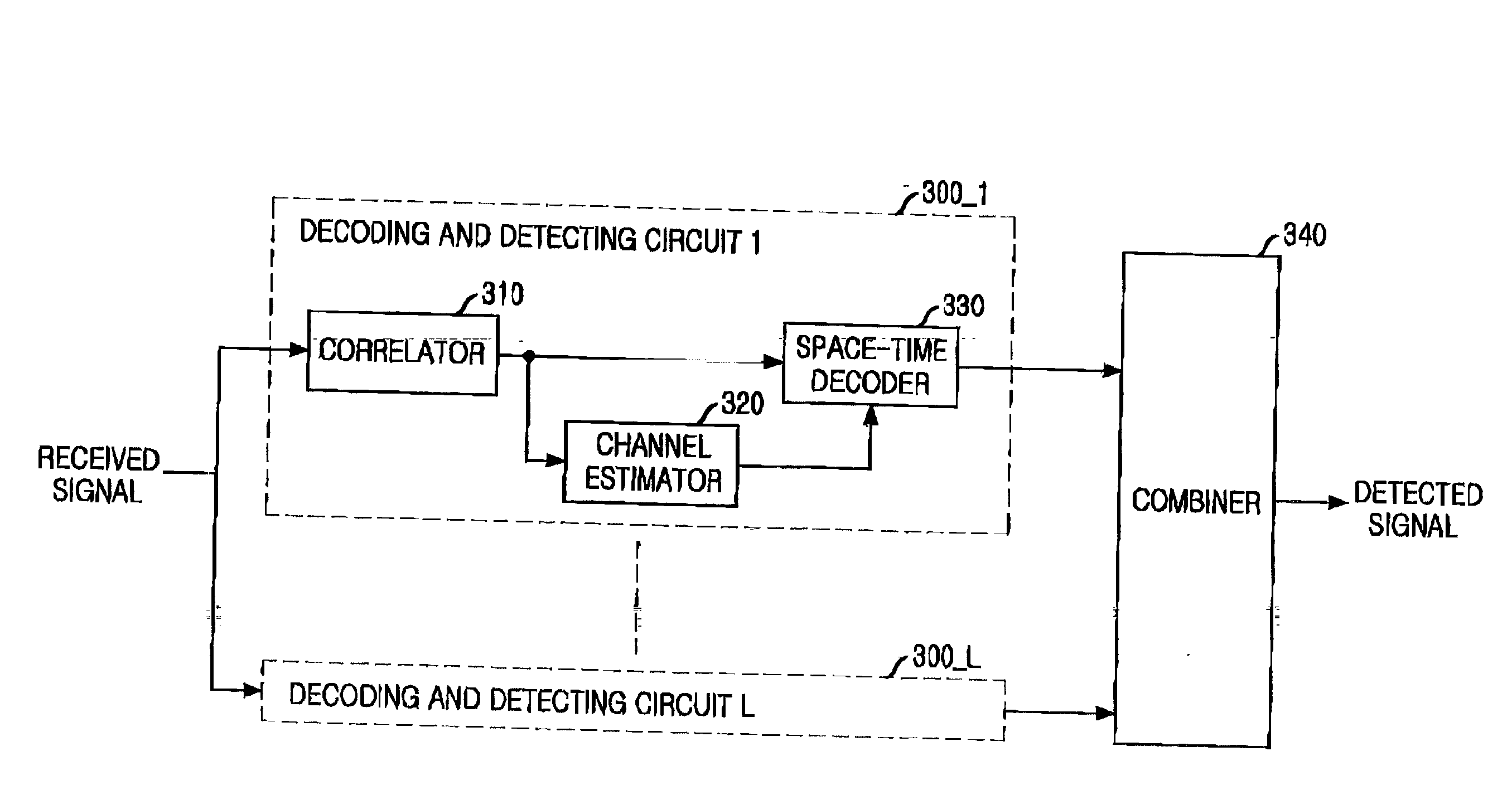
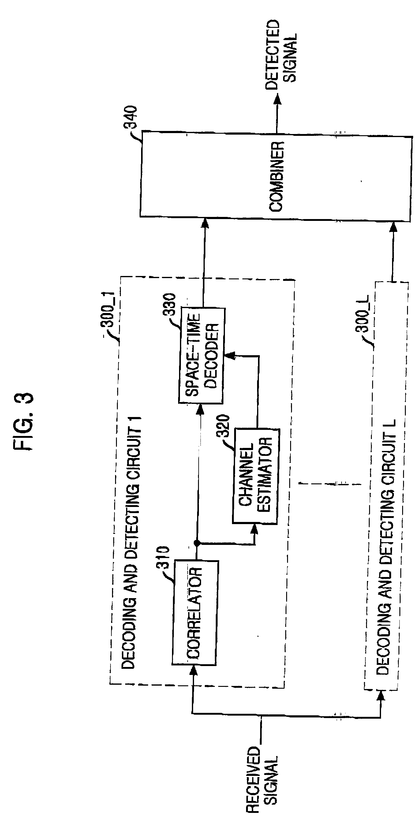
[0036] Referring to FIG. 4, the inventive system is provided with an improved channel estimator and output control device in addition to the conventional system for detecting the signals of space-time coding based on the transmission diversity. The system includes a number L of demodulating and detecting circuits 400.sub.13 1, . . . ,400_L for decoding the signals of respective signal paths to detect data symbols, and a combiner 450 for linearly combining the detected signals from the demodulating and detecting circuit 400.

[0037] Each of the demodulating and detecting circuits 400_1, . . . ,400_L includes a correlator 410 for decoding the received signal into the transmission symbol, channel estimator 420 for calculating the channel estimate, space-time decoder 430 for decoding the space-time coding, and output control device 440 for controlling ...


PUM


Abstract

An apparatus for detecting the signals of transmission diversity based on space-time coding, comprises a plurality of correlators for subjecting received signals to reverse diversification with the same diversity code as used in the transmission side to obtain the transmission symbols decoded, a plurality of channel determiners for obtaining the channel estimates of the slots according to the transmission symbols of the pilot symbol intervals from the correlators to determine the average channel estimate of each symbol through linear interpolation and filtering of the channel estimates, a plurality of space-time decoders for decoding the transmission symbols of the data symbol intervals received from the correlators based on the channel estimates of the channel determiners to detect the data symbols, a plurality of output control devices for comparing the average signal and interference of each slot of the received signals with the threshold value to control the output of the data symbol detected by the space-time decoders, and a combiner for linearly combining the detected signals of the space-time decoders multiplied by the control signals of the output control devices.

Description

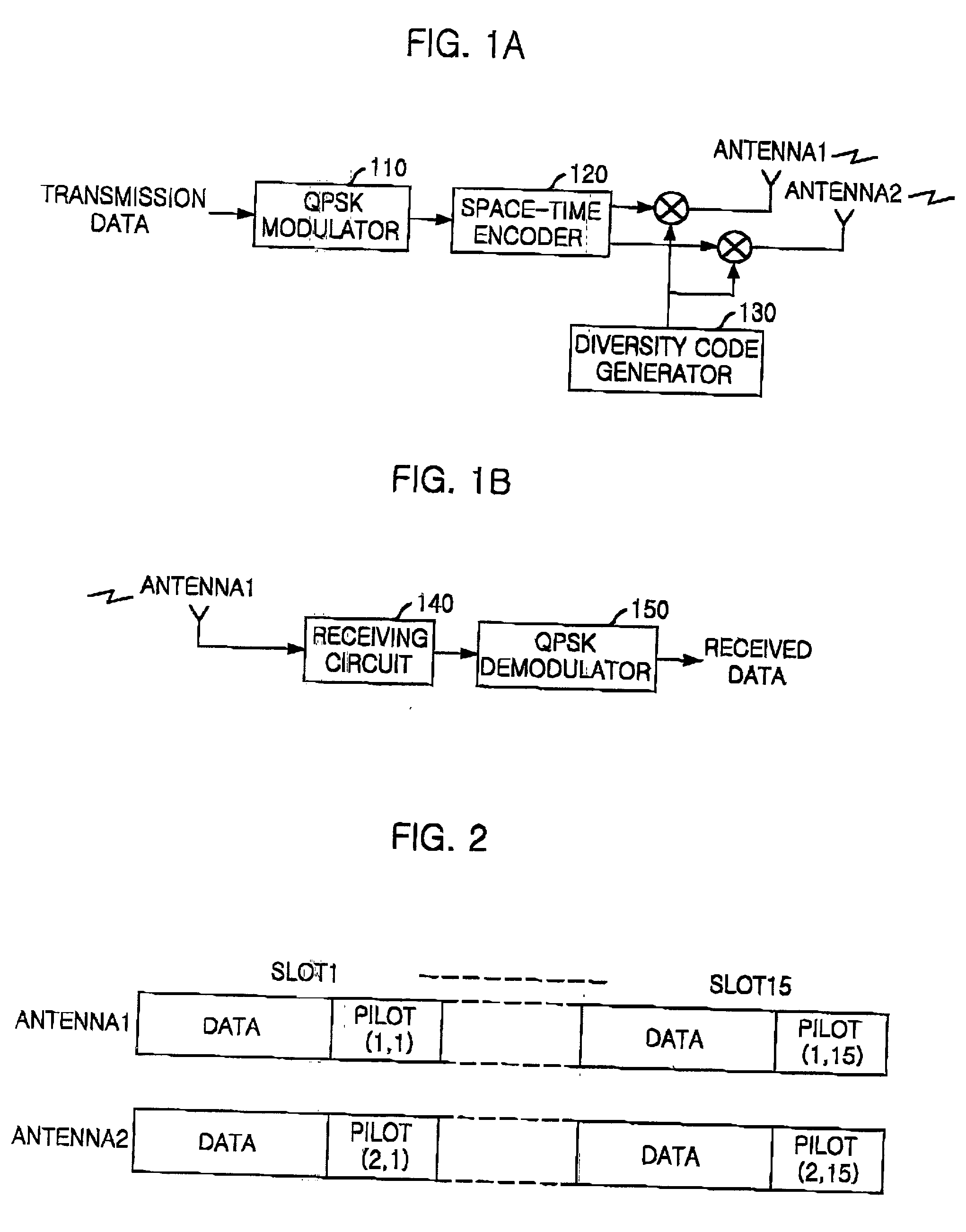
[0001] The present invention relates to an apparatus and method for detecting signals of space-time coding based on transmission diversity, and more particularly an apparatus and method for detecting signals of space-time coding based on transmission diversity, which linearly filter received signals to estimate the average channel gain of each symbol, measure a signal to interference ratio (SIR), and control the decoded output by comparing with the threshold value, thereby detecting correct symbols.DESCRIPTION OF THE PRIOR ART[0002] The multi-path fading occurring in most mobile communication channels serves as the main cause of impeding effective and reliable data transmission. The effect of such fading may be mitigated by the space or antenna diversity. The space diversity method is generally used in the base station, employing the Maximal Ratio Combining receiver to process the signals received through several antennas. However, such space diversity method is not practical for a ...

Claims


Application Information

Patent Timeline
Patent Type & Authority Applications(United States)
IPC IPC(8): H04L1/06H04B7/02
CPCH04L1/0618H04B7/02
Inventor KIM, YEON-SOOSHIN, YOUNG-HEELEE, JOON-HO
Owner KT CORP
Learn More