Heating vest system

a heating vest and heating element technology, applied in the direction of heater elements, contraceptive devices, vibration massage, etc., can solve the problem of difficulty for some individuals to maintain the heating and vibrating elements in the correct locations

Inactive Publication Date: 2001-12-11
BLOODWORTH VICKY W
View PDF13 Cites 72 Cited by
  • Summary
  • Abstract
  • Description
  • Claims
  • Application Information

AI Technical Summary

Benefits of technology

FIG. 1 is a backside, perspective view of the heating vest system of the present invention showing a heating vest system including a vest assembly, a control panel and a DC power source; the vest assembly including a back vibrating heating pad structure, a left shoulder vibrating heating pad structure, a right shoulder vibrating heating pad structure, and a neck vibrating heating pad structure; the control panel having separate heat and vibration controls for each of the back, left shoulder, right shoulder and neck vibrating heating pad structures; the control panel controlling power flow between a DC power supply source and the vibrating and heating elements of the back, left should, right shoulder and vibrating heating pad structures; the neck vibrating heating pad structure being detachably mechanically connectable to an upper edge of the back vibrating heating pad structure; the left shoulder vibrating heating pad structure including a bottom front vest portion having a loop through which a left vest portion securing strap is passed with

Problems solved by technology

Although some areas of the body pose little problem to applying heat and vibration, it can be difficult for some individ

Method used


Image

  • Heating vest system
  • Heating vest system
  • Heating vest system

Examples


Embodiment Construction

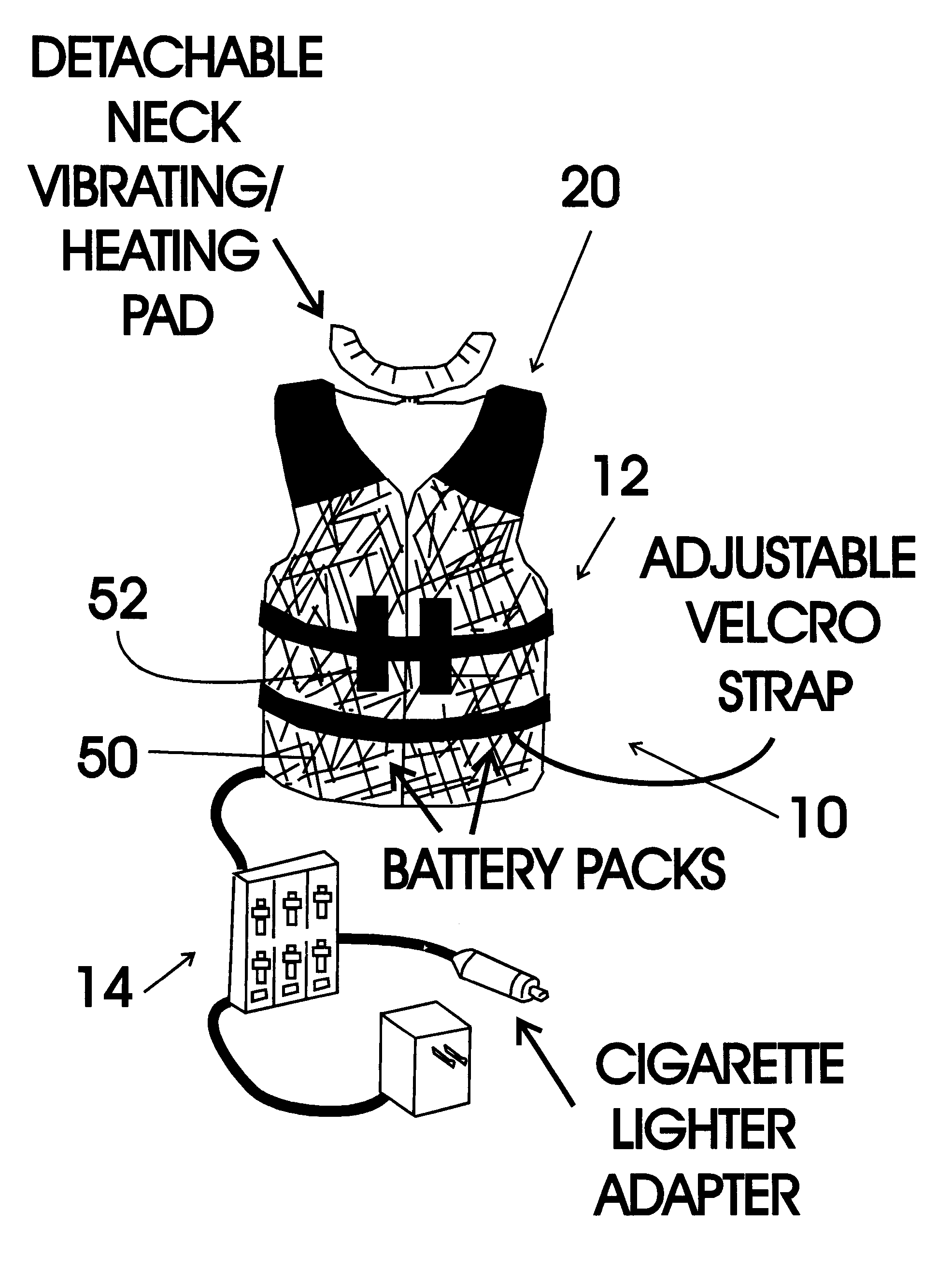
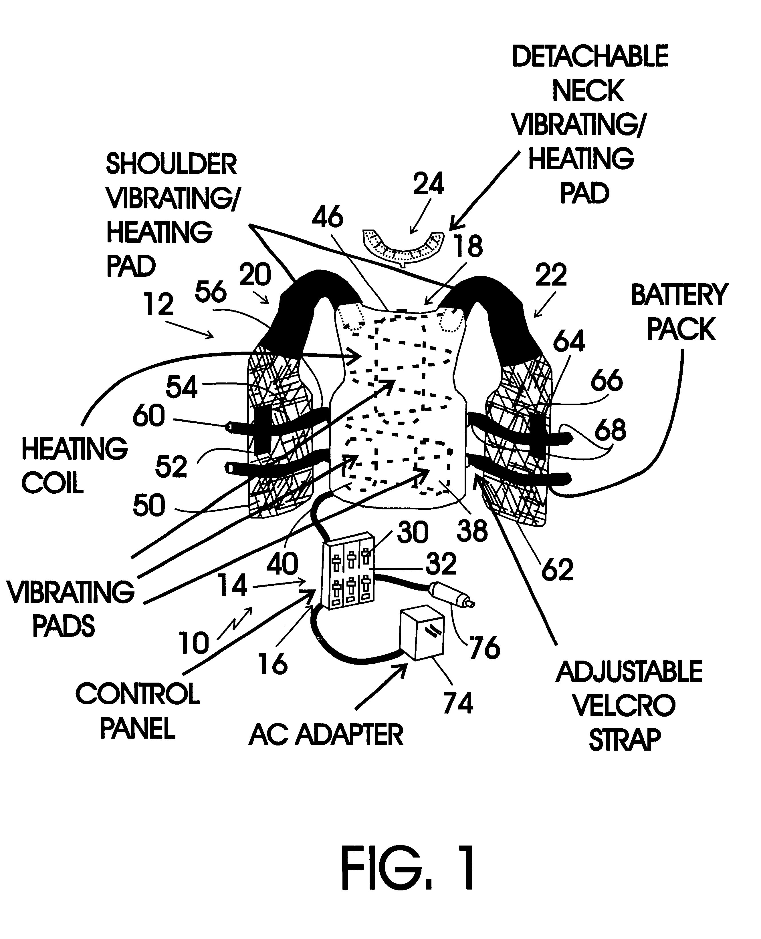
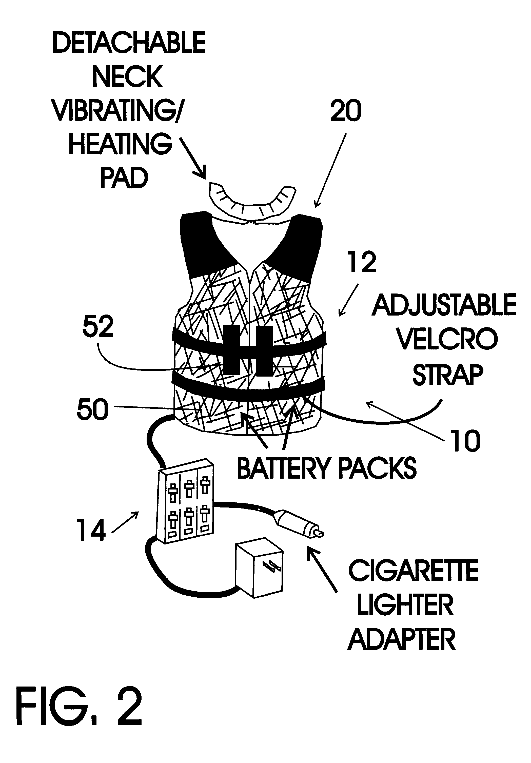
FIGS. 1 and 2 show various aspects of an exemplary embodiment of the heating vest system of the present invention generally designated 10. Heating vest system 10 includes a vest assembly, generally designated 12; a control panel, generally designated 14; and a DC power source, generally designated 16.

Vest assembly 12 includes a back vibrating heating pad structure, generally designated 18; a left shoulder vibrating heating pad structure, generally designated 20; a right shoulder vibrating heating pad structure, generally designated 22 and a detachably connectable neck vibrating heating pad structure, generally designated 24. Control panel 14 has separate heat and vibration controls 30, 32 for each of the back 18, left shoulder 20, right shoulder 22 and neck vibrating heating pad structures 24 plus two additional sets of controls 30, 32 for addition items. Control panel 14 controls power flow between the DC power supply source 16 and the vibrating elements 40 and heating elements 30 ...


PUM


Abstract

A heat vest system that includes a garment wearable by the user having strategically located vibration and heating elements which is worn by the user such that the heating and vibration elements are correctly positioned for a therapeutic effect. To increase the therapeutic effect, the system includes a control device in connection with the vibration and heating elements of the garment which allows the user to separately adjust the heat and vibration generated by each of the heating and vibration elements.

Description

The present invention relates to heating and vibrating appliances and more particularly to a heating vest system that includes a vest assembly, a control panel and a DC power source; the vest assembly including a back vibrating heating pad structure, a left shoulder vibrating heating pad structure, a right shoulder vibrating heating pad structure, and a neck vibrating heating pad structure; the control panel having separate heat and vibration controls for each of the back, left shoulder, right shoulder and neck vibrating heating pad structures; the control panel controlling power flow between the DC power supply source and the vibrating and heating elements of the back, left should, right shoulder and vibrating heating pad structures; the neck vibrating heating pad structure being detachably mechanically connectable to an upper edge of the back vibrating heating pad structure; the left shoulder vibrating heating pad structure including a bottom front vest portion having a loop throu...

Claims


Application Information

Patent Timeline
IPC IPC(8): A61H23/02H05B3/34A61F7/02
CPCA61H23/02H05B3/342A61F7/007A61F2007/0234A61H2201/0207A61H2201/0228A61H2201/165A61H2205/04A61H2205/08H05B2203/014H05B2203/036
Inventor BLOODWORTH, VICKY W.
Owner BLOODWORTH VICKY W
Why Eureka
Try Eureka