Mounting system for a circuit breaker

Inactive Publication Date: 2001-12-18
PROLEC GE INT S DE R L DE
View PDF11 Cites 6 Cited by
  • Summary
  • Abstract
  • Description
  • Claims
  • Application Information

AI Technical Summary

Problems solved by technology

This causes that the elongated winding connection of the circuit breaker had to pass over the movable elongated cutter pin, interfering with the operation thereof, causing in turn a continuous friction of the winding connection which, shortly, may cause short circuits and undesire

Method used


Image

  • Mounting system for a circuit breaker
  • Mounting system for a circuit breaker
  • Mounting system for a circuit breaker

Examples


Embodiment Construction

.

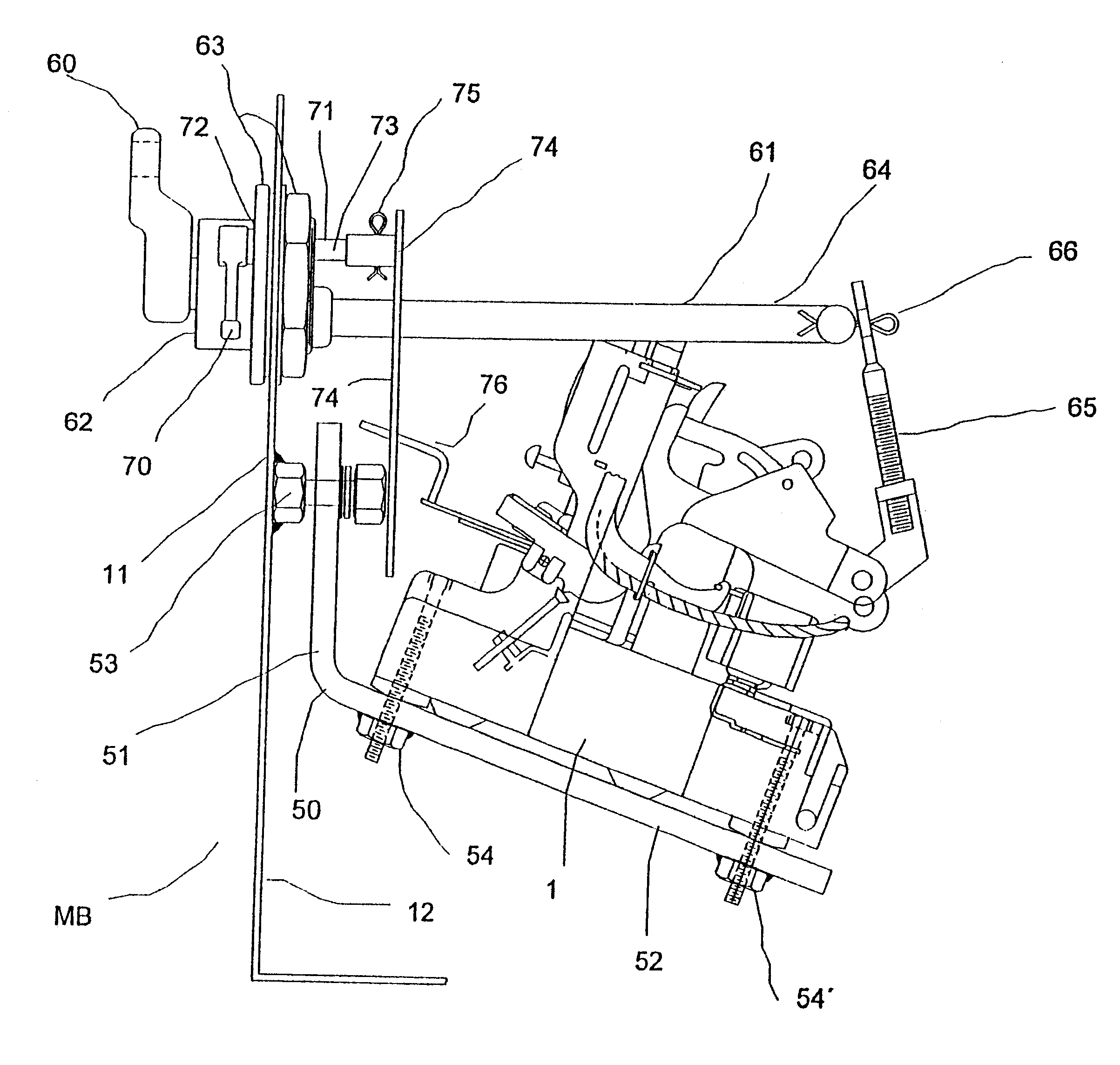
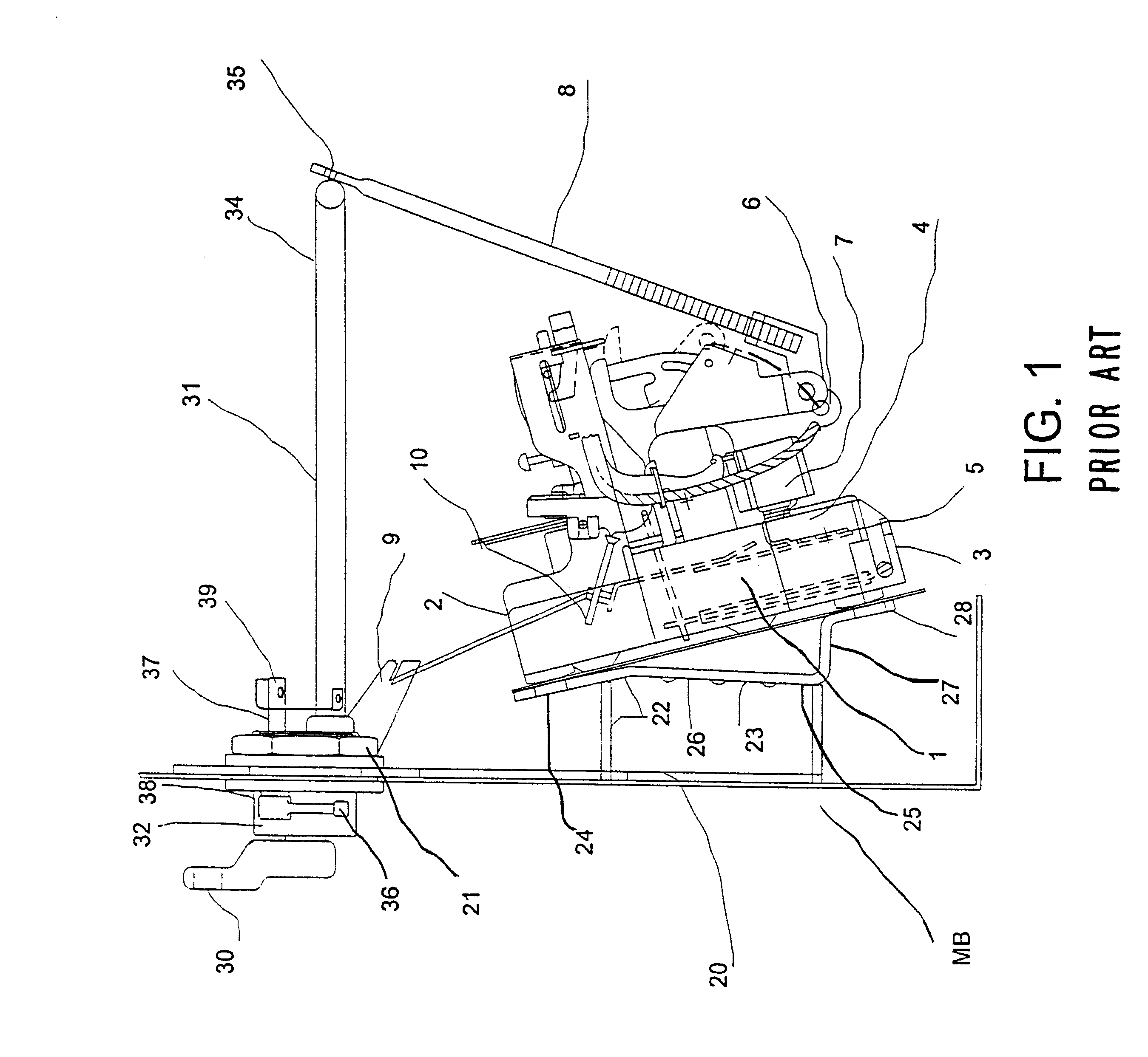
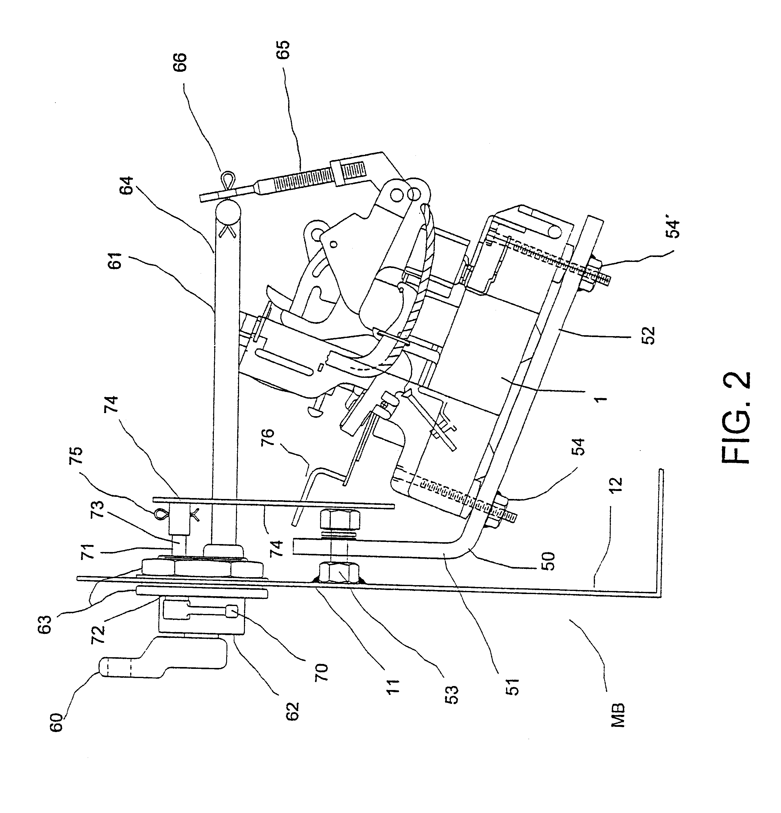
The invention will now be described in the following by firstly describing a circuit breaker in a very general way, as a starting reference and which is not the object of the present invention, then a known mounting system designed for transformers and afterwards the mounting system for circuit breakers in accordance with the present invention.

Commercial circuit breakers, including an overload unit, such as those produced and existing in the commerce by ERMCO, are well known in the art for many purposes, and comprising: a circuit breaker body 1 including internal breaking components (not illustrated), an upper end 2 and a lower end 3, a winding elongated connection 4 and a low tension elongated connection 5, a fixed break contact 6 and a movable break contact 7, by means of which the circuit breaker is operated on and off, mounted in a hinged fashion on the circuit breaker body 1, having an actuator rod 8, and an overload actuator 9, connected to an actuator pin 10.

Said movable bre...


PUM


Abstract

A mounting system for a circuit breaker comprising: a mounting box; an angular mounting plate, including a planar portion retained to a mounting wall of a mounting box, and an angular portion at about 200° in which a circuit breaker body is retained; a mechanical breaker actuator handle, retained to the mounting wall, including an actuator bar coupled to the breaker actuator handle; an actuator rod coupled to the actuator bar of the breaker actuator handle, and to a movable break contact of the circuit breaker, in order to operate it against a fixed breaker contact, on and off, by a rotational operation of the breaker actuator handle; and an overload actuator handle including a short overload actuator arm coupled to the overload actuator handle; and a link arm coupled to the overload actuator arm, in order to operate it, on and off, by a rotational operation of the overload actuator handle.

Description

A. Field of the InventionThe present invention refers to a circuit breaker and, more specifically to a simplified mounting system for a circuit breaker of the type used in transformers.B. Description of the Related ArtThermal or thermo-magnetic circuit breakers, including an overload unit, such as those existing in the commerce, are well known in the art for many purposes.Said circuit breakers including a circuit breaker body including the breaking components and having a fixed break contact and a movable break contact mounted in a hinged fashion on the circuit breaker body, which is to be mechanically operated by a mounting system.For distribution transformers, an specific mounting system for such circuit breaker was developed by the inventor of the present invention, which is now in commerce.Said now known mounting system was constituted by a mounting plate including retained at mounting wall of a mounting box, including a five pieces support bench presenting a first mounting surf...

Claims


Application Information

Patent Timeline
IPC IPC(8): H02B1/00H02B1/48H01H9/02H01H3/02H01H3/04
CPCH02B1/48H01H3/04H01H9/02
Inventor MALDONADO-CORTES, DEMOFILO
Owner PROLEC GE INT S DE R L DE
Why Eureka
Try Eureka