Image display panel employing a broad-band polarizing/reflective backlighting structure and a pixelated array of reflective-type of filtering elements

a technology of image display panel and polarizing/reflective backlighting structure, which is applied in the direction of polarising elements, solar heat collector controllers, mechanical pattern conversion, etc., can solve the problems of light transmission, inability to produce high brightness images from prior art color lcd panels used in direct or projection display systems, and achieve high brightness color images, avoiding shortcomings and drawbacks

Inactive Publication Date: 2001-12-25
REVEO
View PDF15 Cites 22 Cited by
  • Summary
  • Abstract
  • Description
  • Claims
  • Application Information

AI Technical Summary

Benefits of technology

Accordingly, a primary object of the present invention is to provide an improved color LCD panel capable of producing high brightness color images, while avoiding the shortcomings and drawbacks of prior art techniques.
FIG. 14 is a schematic representation of an exploded, cross-sectional view of an exemplary pixel structure within a fourth embodiment of the LCD panel shown in FIG. 8, wherein the spatial-intensity modulating elements of the LCD panel are realized using circular-type polarization rotating elements, the pixel driver signals provided thereto are selected to produce "bright" output levels the red and blue subpixels of the exemplary pixel structure and a "dark" output level at the green subpixel level, and a broad-band absorptive linear polarizer is used in conjunction with each broad-band polarizing reflective panel in the LCD panel in order to provide improved image contrast in the images displayed therefrom; and

Problems solved by technology

However, using prior art design techniques, it has been impossible to achieve this design goal due to significant losses in light transmission caused by the following factors, namely: absorption of light energy due to absorption-type polarizers used in the LCD panels; absorption of light reflected off thin-film transistors (TFTs) and wiring of the pixelated spatial intensity modulation arrays used in the LCD panels; absorption of light by pigments used in the spectral filters of the LCD panels; absorption of light energy by the black-matrix used to spatially separate the subpixel filters in the LCD panel in order to enhance image contrast; and Fresnel losses due to the mismatching of refractive indices between layers within the LCD panels.
Thus, it is impossible to produce high brightness images from prior art color LCD panels used in either direct or projection display systems without using ultra-high intensity backlighting sources which require high power supplies, and produce great amounts of heat necessitating cooling measures and the like.
However, such prior art color LCD panel designs are not without shortcomings and drawbacks.
Consequently, prior art LCD panels have very low light transmission efficiencies.
Thus the production of high brightness color images from prior art LCD panels has required high-intensity backlighting sources which consume great amounts of electrical power and produce high quantities of heat, and necessitate the use of fans and other cooling measures to maintain the temperature of both the LCD panel and the lamp(s) in the backlight structure within safe operating limits.

Method used


Image

  • Image display panel employing a broad-band polarizing/reflective backlighting structure and a pixelated array of reflective-type of filtering elements
  • Image display panel employing a broad-band polarizing/reflective backlighting structure and a pixelated array of reflective-type of filtering elements
  • Image display panel employing a broad-band polarizing/reflective backlighting structure and a pixelated array of reflective-type of filtering elements

Examples


Embodiment Construction

Referring now to the figures in the accompanying Drawings, the illustrative embodiments of the present invention will now be described in detail, wherein like structures and elements shown within the figures are indicated with like reference numerals.

Overview of the LCD Image Display System of Present Invention

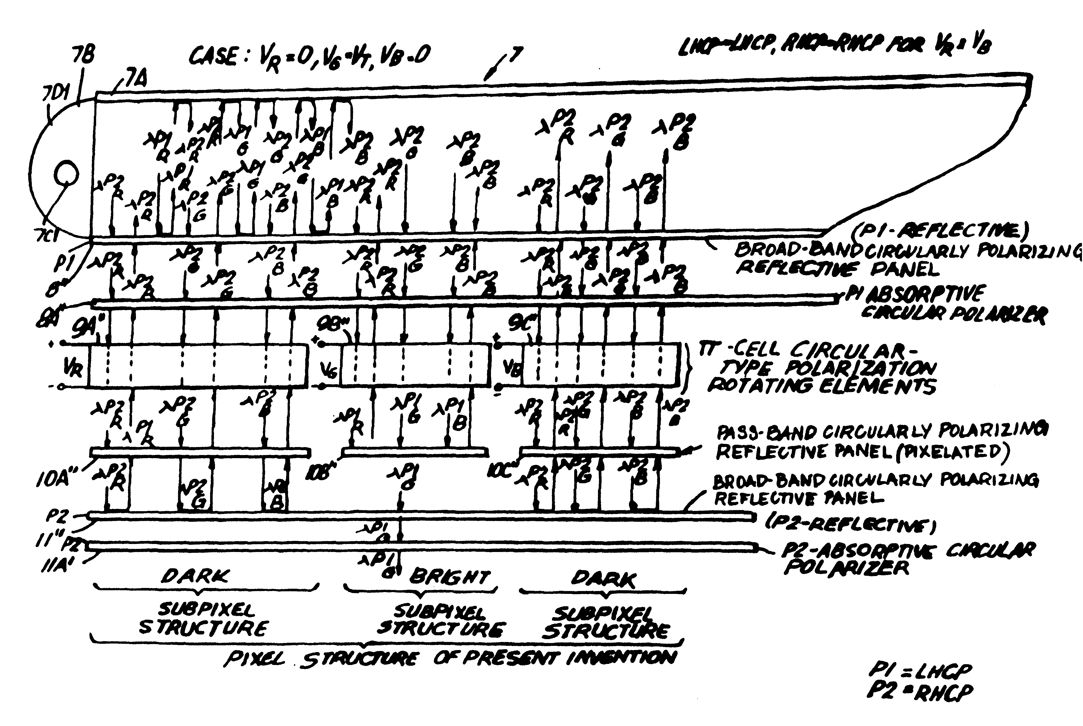
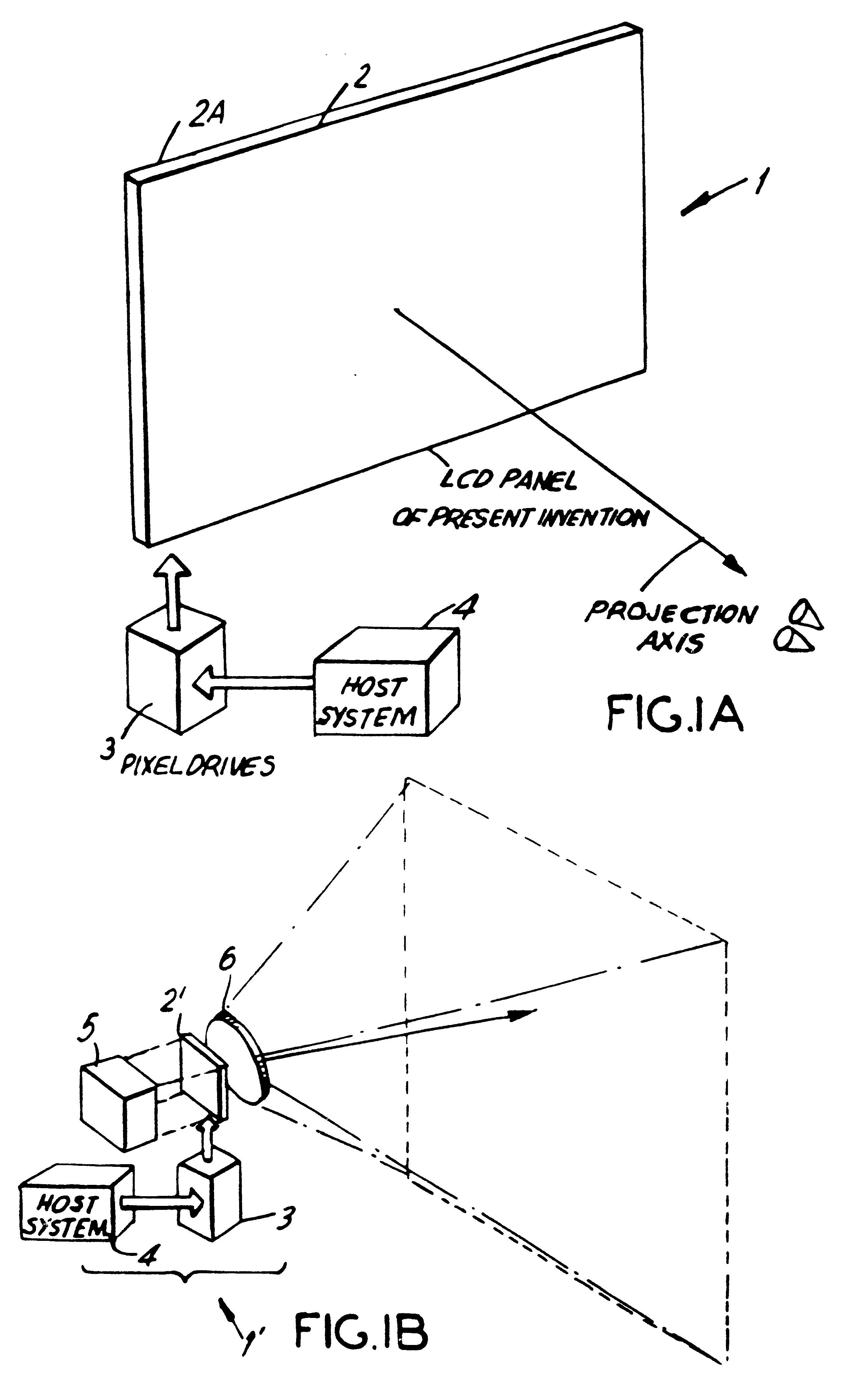
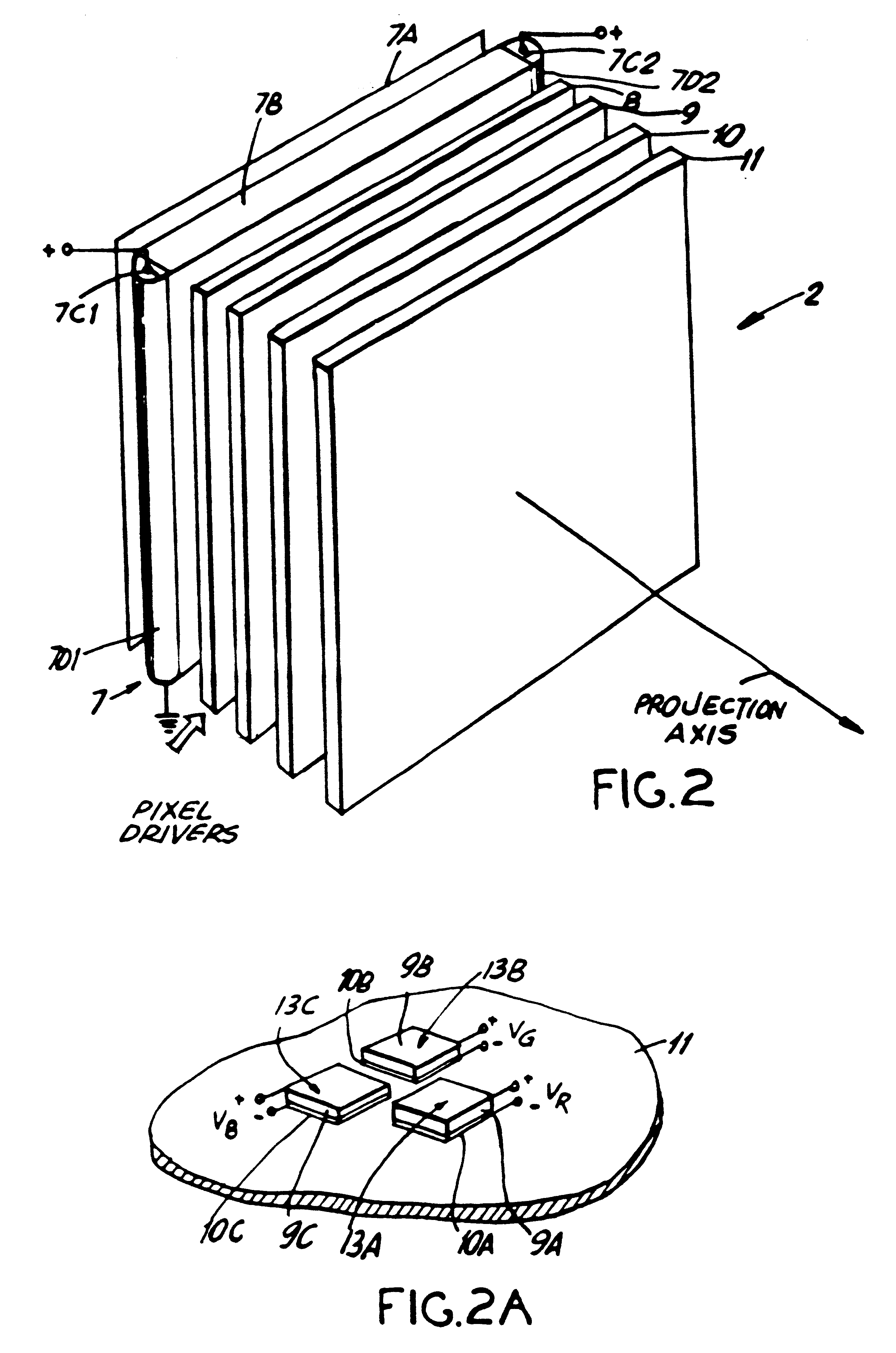
As shown in FIG. 1A, the LCD panel of the present invention is shown as part of a direct-view type color image display system 1 which is capable of supporting displaying high-resolution color images. During operation, the LCD panel 2 is actively driven by pixel driver circuitry 3 in response to color image data sets produced from a host system 4 which can be a computer-graphics board (subsystem), a video source (e.g. VCR), camera, or like system. The function of the LCD panel 2 is to spatial intensity modulate and spectrally filter on a subpixel basis the light emitted from an edge-illuminated backlighting structure 2A which may be realized in a variety of ways. The optically ...


PUM

PropertyMeasurementUnit
brightnessaaaaaaaaaa
wavelengthsaaaaaaaaaa
electromagnetic spectrumaaaaaaaaaa

Abstract

A liquid crystal display (LCD) panel construction for producing color images for viewing by a viewer. The LCD panel construction comprises: an illumination panel for producing light including spectral components with wavelengths in a visible band of the electromagenetic spectrum; a plurality of pixel regions within a predefined image display area, wherein each pixel region has a plurality of subpixel region and each said subpixel region within each pixel region has a light transmission portion and a light blocking portion, and each light transmission portion and light blocking portion has a frontside disposed in the direction in the viewer and a backside in the direction of the illumination panel. The illumination panel illuminates the plurality of pixel regions from the backside thereof so that a color image is formed the said plurality of pixel regions for viewing. A pattern of broad-band reflector material is disposed in spatial registration with the backside of the light blocking portions of the subpixel regions, for reflecting produced light at structures associated with the light blocking portions of the subpixels, thereby recycling produced light for use in illuminating said plurality of pixel regions. A pattern of broad-band absorption material is also disposed in spatial registration with the frontside of the light blocking portions of the subpixel regions, for absorbing ambient light incident upon structures associated with the light blocking portions of the subpixels, thereby reducing glare at the surface of the LCD panel due to ambient light incident thereon.

Description

BACKGROUND OF INVENTION1. Technical FieldThe present invention relates to a high-brightness color liquid crystal display (LCD) panel with improved image contrast employing non-absorptive spectral filtering, light recycling among neighboring subpixels and ambient glare reduction, and also to methods and apparatus for manufacturing the same.2. Brief Description of the Prior ArtWithout question, there is a great need for flat display panels capable of displaying video imagery in both direct and projection modes of viewing. Examples of equipment requiring such display structures for direct viewing include notebook computers, laptop computers, and palmtop computers, and equipment requiring such display structures for projection viewing include LCD projection panels and LCD image projectors.In general, prior art color LCD display panels have essentially the same basic construction in that each comprises the following basic components, namely: a backlighting structure for producing a plane...

Claims


Application Information

Patent Timeline
Patent Type & Authority Patents(United States)
IPC IPC(8): F24J2/40G01D11/28G02F1/1335G02F1/13G02B27/00G02B5/30G02F1/1334G02B30/25G02F1/13357G03B21/132G03B21/30G06F1/16G06F3/00G06F3/01G06F3/033G06F3/041G06F3/048G09G3/20G09G3/36H04N5/74
CPCB82Y15/00F24J2/407G01D11/28G02B5/3016G02B27/0093G02B27/26G02F1/133514G02F1/13362G02F1/133621G03B21/132G03B21/30G06F1/1616G06F1/1626G06F1/1639G06F3/011G06F3/041G06F3/0412G06F3/0414H04N5/7441H04N9/3141Y02E10/40G02F1/1334G02F1/133536G02F2001/133538G02F2001/133623G02F2001/133627H04N5/7491E06B2009/2464F24S50/80G02B30/25G02F1/133538G02F1/133623G02F1/133627G02F1/1335
Inventor FARIS, SADEG MUSTAFA
Owner REVEO
Why Eureka
Try Eureka