
Piezoelectric/electrostrictive device and production method thereof

a technology of electro-electrostrictive device and production method, which is applied in piezoelectric/electrostrictive/magneto-strictive device, piezoelectric/electrostriction/magneto-striction machine, electrical apparatus, etc., and can solve the problems of low mechanical strength, easy to be influenced, and low impact resistance and humidity resistan

Inactive Publication Date: 2002-01-01
NGK INSULATORS LTD
View PDF4 Cites 30 Cited by
  • Summary
  • Abstract
  • Description
  • Claims
  • Application Information

AI Technical Summary

Problems solved by technology

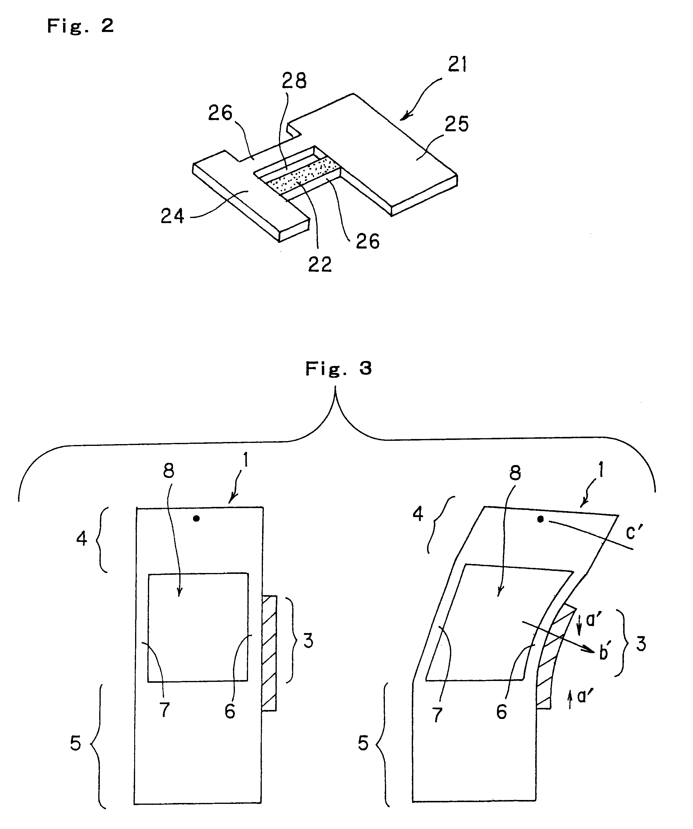
However, the actuator 21 has a problem that an operational quantity of the movable portion 24 is small, since the displacement in an expanding or contracting direction (namely, the in-plane direction of the board-like body) of a piezoelectric / electrostrictive material is transmitted per se to the movable portion.
Further, the actuator 21 has another problem that the actuator 21, having all the parts thereof constituted with a piezoelectric / electrostrictive material which is fragile and comparatively heavy, is low in mechanical strength, and inferior in handling property, impact resistance and humidity resistance, and further the actuator 21 per se is heavy and is easily influenced by a harmful vibration, for example, residual vibration or vibrational noise during high speed operation.
However, it is apparent that efficiency of the displacement due to the inverse piezoelectric effect or the electrostrictive effect is lowered when the filler is added.
In addition, the actuator disclosed in JP-A-63-64640 has a structure where a displacement generating member and a so-called frame member (an intermediary member or the like) are prepared separately, and adhered mutually to unite, thus the structure is liable to change over time the bonding condition of the frame and the bimorph, and also liable to cause drifting of the displacement, exfoliation, or the like.
Further, a structure with an adhesive intervened at the bonding site of the bimorph with the intermediary member and at the bonding site of the head with the bimorph, namely at a holding portion of a displacement member, is lower in stiffness at the holding portion per se, thus making it difficult to increase a resonant frequency required for high speed operation.

Method used


Image

  • Piezoelectric/electrostrictive device and production method thereof
  • Piezoelectric/electrostrictive device and production method thereof
  • Piezoelectric/electrostrictive device and production method thereof

Examples


example 1

LAMINATING EXAMPLE 1

ceramic green sheet 1 (hereinafter called "GS") for forming a thin plate, a holed GS 1, a holed GS 2, a holed GS 3, a holed GS 4, and a holed GS 2, as shown in FIG. 32, are overlaid in the sequence, then compressed to produce an integrated ceramic green laminate.

example 2

LAMINATING EXAMPLE 2

Step 1: A GS1 for forming a thin plate is placed over a holed GS1, then the sheets are compressed to produce an integrated ceramic green laminate.

Step 2: A holed GS4 is placed over a thin plate forming ceramic green sheet 2, then the sheets are compressed to produce an integrated ceramic green laminate.

Step 3: An integrated ceramic green laminate obtained in step 1, a holed GS2, a holed GS3, an integrated ceramic green laminate obtained in step 2 are overlaid in the sequence, and then compressed to produce an integrated ceramic green laminate.

example 3

LAMINATINED EXAMPLE 3

Step 1: A holed GS1, a holed GS2, a holed GS3, a holed GS4 are overlaid in the sequence, and then compressed to produce an integrated ceramic green laminate.

Step 2: A GS1 for forming a thin plate, an integrated ceramic green laminate obtained in step 1, and a thin plate forming GS2 are overlaid in the sequence, and then compressed to produce an integrated ceramic green laminate.


PUM

PropertyMeasurementUnit
Lengthaaaaaaaaaa
Mechanical strengthaaaaaaaaaa
Thicknessaaaaaaaaaa

Abstract

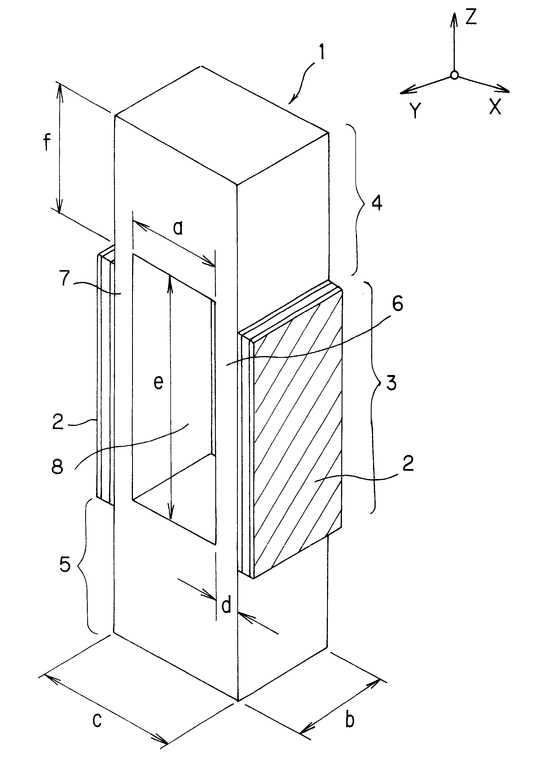
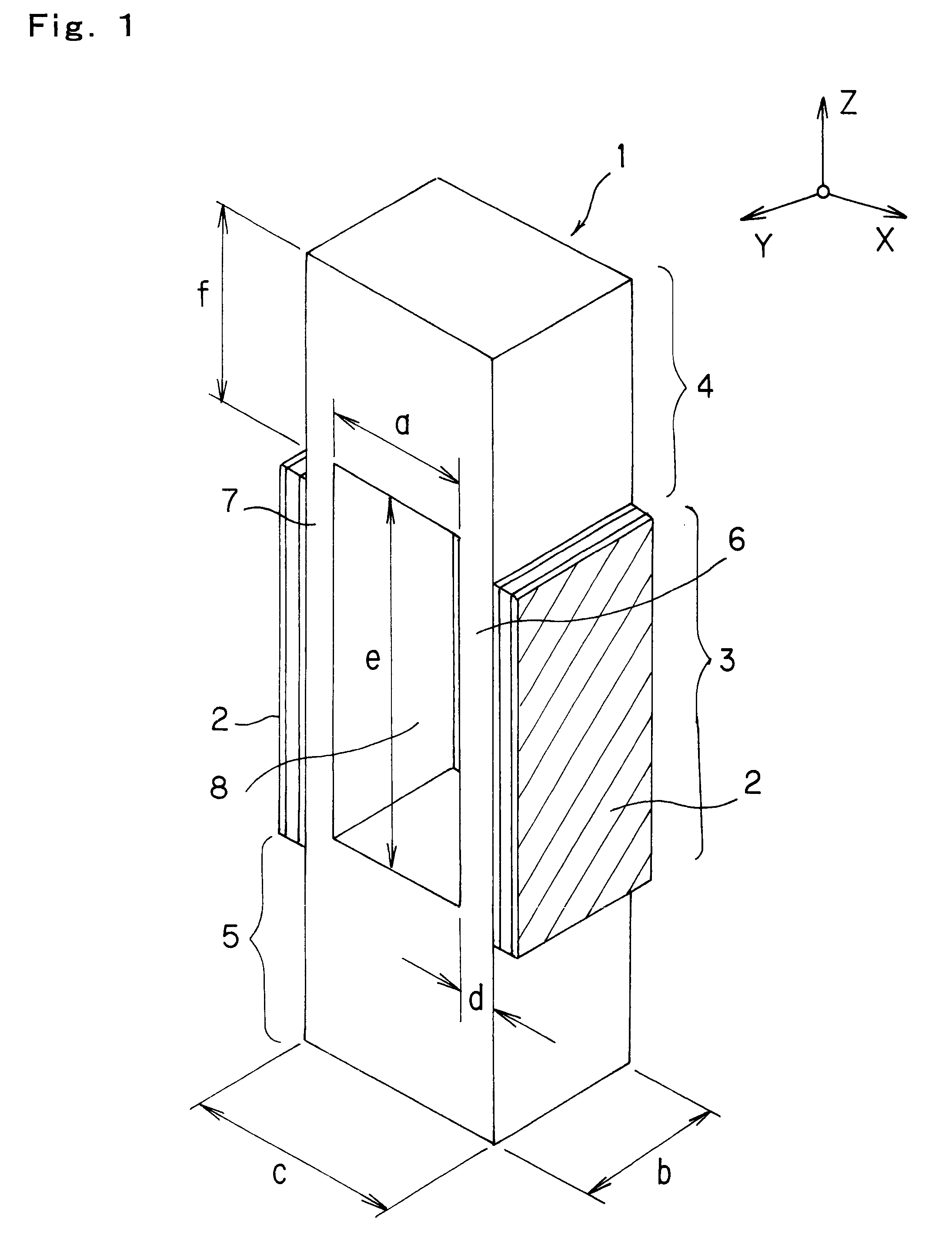
A piezoelectric / elecrostrictive device comprising a driving portion to be driven by a displacement of a piezoelectric / electrostrictive element, a movable portion to be operated based on a drive of the driving portion, and a fixing portion for holding the driving portion and the movable portion. The driving portion comprises a pair of thin plate portions facing each other, and a film-like piezoelectric / electrostrictive element including at least a pair of electrode films and a piezoelectric / electrostrictive film formed at least on the outer surface of at least one thin plate portion of the thin plate portions. The fixing portion is coupled with the movable portion via the driving portion, a hole is defined by an inner wall of the driving portion, an inner wall of the movable portion, and an inner wall of the fixing portion, and at least one side of a piezoelectric operating portion of said piezoelectric / electrostrictive element in a direction in which said thin plate portion connects with said fixing portion with the movable portion is structured to exist on the fixing portion or the movable portion. A ratio a / b of the thickness a of said hole and the width b of said thin plate portion is 0.5 to 20. Since the movable portion can be largely operated, the device can be used as a displacement element which is hardly affected by a harmful vibration in operation, and superior in mechanical strength, handling property, impact resistance, and humidity resistance, and a sensor element capable of detecting a vibration of the movable portion with fine precision.

Description

BACKGROUND OF THE INVENTION AND RELATED STATEMENTThe present invention relates to a piezoelectric / electrostrictive device having a movable portion to be operated based on a displacement of a piezoelectric / electrostrictive element, or a piezoelectric / electrostrictive device capable of detecting a displacement of the movable portion by the piezoelectric / electrostrictive element, and more particularly relates to a piezoelectric / electrostrictive device which is superior in mechanical strength, impact resistance, and humidity resistance and can efficiently operate the movable portion in a large magnitude.Recently, in a field of optics or magnetic recording, precision machining, or the like, a displacement element capable of adjusting an optical path length and a position in sub-micron order has been required, and development has progressed of a displacement element utilizing a displacement due to the inverse piezoelectric effect or electrostrictive effect obtained when a voltage is appli...

Claims


Application Information

Patent Timeline
IPC IPC(8): H01L41/24H01L41/09
CPCH01L41/0946H01L41/314Y10T29/42Y10T29/49002Y10T29/4902Y10T29/49078Y10T29/49798Y10T29/49126Y10T83/0577Y10T83/0476Y10T83/0505Y10T83/051H10N30/2043H10N30/074
Inventor TAKEUCHI, YUKIHISANANATAKI, TSUTOMUHIROTA, TOSHIKAZUKIMURA, KOJI
Owner NGK INSULATORS LTD
Learn More