Cathoderay tube

Inactive Publication Date: 2002-01-15
KK TOSHIBA
View PDF12 Cites 16 Cited by
  • Summary
  • Abstract
  • Description
  • Claims
  • Application Information

AI Technical Summary

Benefits of technology

It is an object of the present invention to provide a color cathode-ray tube in which the sideways expansion of a beam spot is eliminated or reduced, despite o

Problems solved by technology

Thus, the beams can form undistorted spots on any region of the screen.
If such a mean is used, however, a problem arises when the astigmatism caused by the deflecting yoke is very strong at t

Method used


Image

  • Cathoderay tube
  • Cathoderay tube
  • Cathoderay tube

Examples


Embodiment Construction

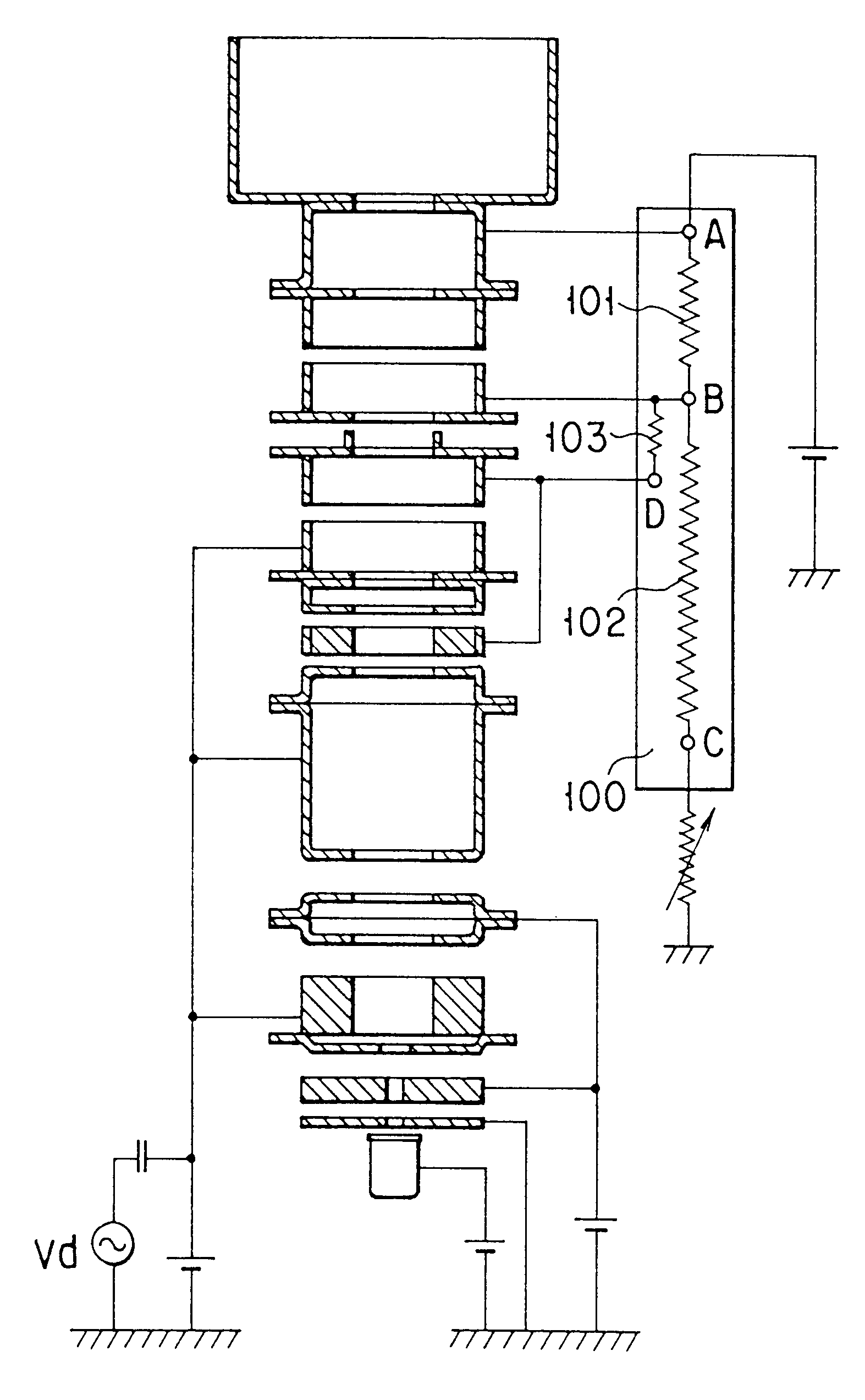
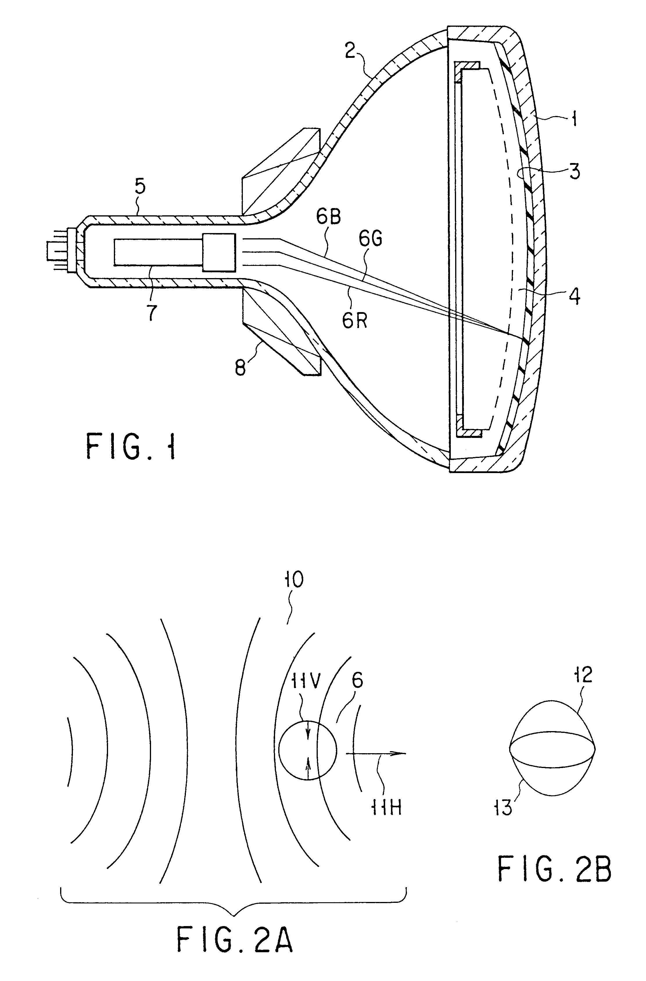
The electron gun assemblies incorporated in cathode-ray tubes according to an embodiment of the present invention will be described with reference to the accompanying drawings.

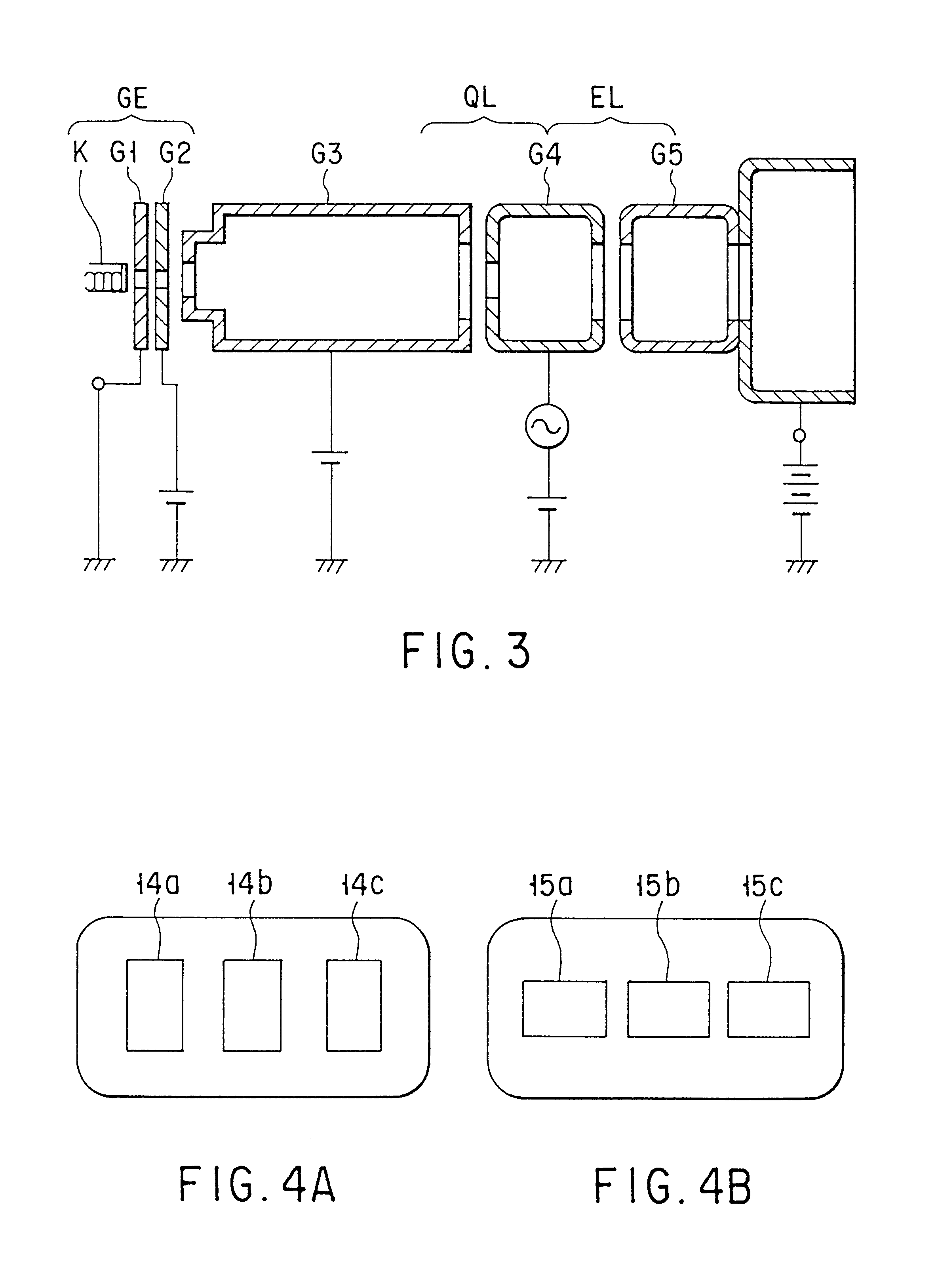
FIGS. 7A and 7B are cross-sectional views showing the electron gun assembly incorporated in a cathode-ray tube according to the first embodiment of the present invention. As FIG. 7A shows, three cathodes KB, KG and KR, first to eighth grids 1 to 8, and a convergence cup are arranged in the order mentioned are secured to an insulated support (not shown). The cathodes KB, KG and KR contain a heaters (not shown) each, for generating an electron beam.

The first grid 1 is a thin electrode having three electron beam guide holes of a small diameter. The second grid 2 is a thin electrode having three electron beam guide holes of a small diameter. The third grid 3 comprises a thick electrode and a cup-top electrode combined with the thick electrode. The third grid 3 has three electron beam guide holes made in the side f...


PUM


Abstract

An electron gun assembly of a cathode ray tube has a main electron lens section comprising at least four electrodes, provided in a sequence of first, second, third and fourth grids, a middle first voltage is applied to the first grid, and an anode voltage is applied to the fourth grid. The adjacent second grid and third grid are connected by a resistor, and second and third voltages of substantially the same potential, corresponding to voltages higher than the middle first voltage and lower than the anode voltage, are applied thereto. An asymmetrical lens is provided between the adjacent second grid and the third grid second lens region, and a voltage which changes in synchronism with the deflecting magnetic field is applied to the first grid. Therefore, it is possible to provide a cathode ray tube wherein a phenomenon of sideways deviation of an electron beam at the peripheral region of a screen caused by lens magnification difference in the horizontal and vertical directions is reduced, and which has good image characteristics in all regions of the screen.

Description

This invention relates to a cathode-ray tube, and more particularly to a cathode-ray tube incorporating an electron gun assembly which compensates for dynamic astigmatism.Generally, a color cathode ray art tube has an envelope as shown on FIG. 1. The envelope comprises a panel 1 and a funnel 2 joined to the panel 1. A phosphorous screen 3 (target) is provided on the inner surface of the panel 1. the screen 3 comprises striped or dot-like three-color phosphor layers for generating blue, green, and red light rays. A shadow mask 4 is provided in the funnel 2 and faces the phosphor screen 3. The shadow mask 4 has a large number of aperatures. The funnel 2 has a neck 5, in which an electron gun assembly 7 is provided. A deflection yoke 8 is mounted on the neck 5. The electron gun assembly 7 emits three electron beams 6B, 6G, and 6R. The yoke 8 generates a horizontal magnectic field and a vertical magnetic field. These magnetic fields deflect the electron beams 6B, 6G and 6R in horizontal...

Claims


Application Information

Patent Timeline
IPC IPC(8): H01J29/50
CPCH01J29/503H01J2229/4841H01J29/50
Inventor KIMIYA, JUNICHIAWANO, TAKASHISUGAWARA, SHIGERU
Owner KK TOSHIBA
Why Eureka
Try Eureka