
Tool for removing damaged fasteners and method for making such tool

a technology for fasteners and tools, applied in the field of tools for removing threaded fasteners, can solve the problems of inability to manufacture tools in accordance with conventional manufacturing processes, damage to polygonal sides, and inability to meet the requirements of the application of the tool,

Inactive Publication Date: 2002-01-22
JORDAN CHALMER C
View PDF17 Cites 21 Cited by
  • Summary
  • Abstract
  • Description
  • Claims
  • Application Information

AI Technical Summary

Problems solved by technology

There has been a persistent problem with the polygonal-style threaded fasteners in the prior art when the polygonal sides become worn or damaged the sides no longer define the requisite shape that is necessary for the fastener to cooperate with the tool that is designed for its application and removal.
Frequently this problem arises when the fastener is to be removed and the polygonal sides have been damaged due to corrosion or mechanical wear.
In this situation, the conventional tools that are designed for the removal of the fastener are no longer operative.
Generally, the conventional tool will merely slip over the rounded or damaged corners between the polygonal sides of the fastener so that the tool will not remove the fastener.
This difficulty has been recognized in the prior art wherein different types of tools have been developed for the removal of damaged polygonal fasteners from their threaded members.
One difficulty with the tools for removing damaged fasteners as known in the prior art was that the tools could not be readily manufactured in accordance with conventional manufacturing processes.
Machining the individual teeth into a tool body such as described in U.S. Pat. Nos. 3,996,819 and 5,551,320 was not practical on a commercial scale.
Broaching the teeth into the tool body was also found to be unworkable because the geometry of the tool caused the broach to seize in the tool.
This resulted in the destruction of either the broach or the tool, or both.

Method used


Image

  • Tool for removing damaged fasteners and method for making such tool
  • Tool for removing damaged fasteners and method for making such tool
  • Tool for removing damaged fasteners and method for making such tool

Examples


Embodiment Construction

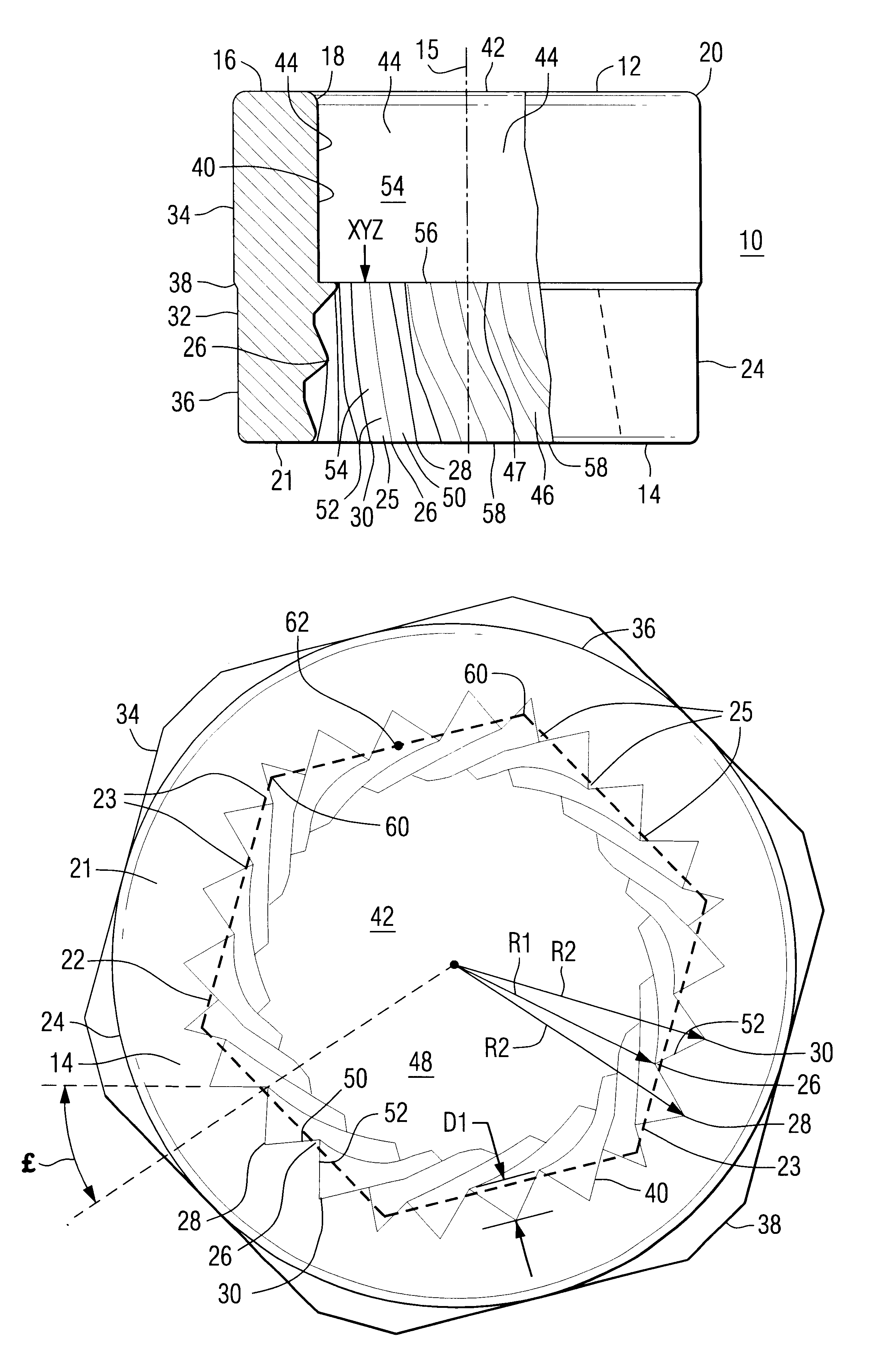
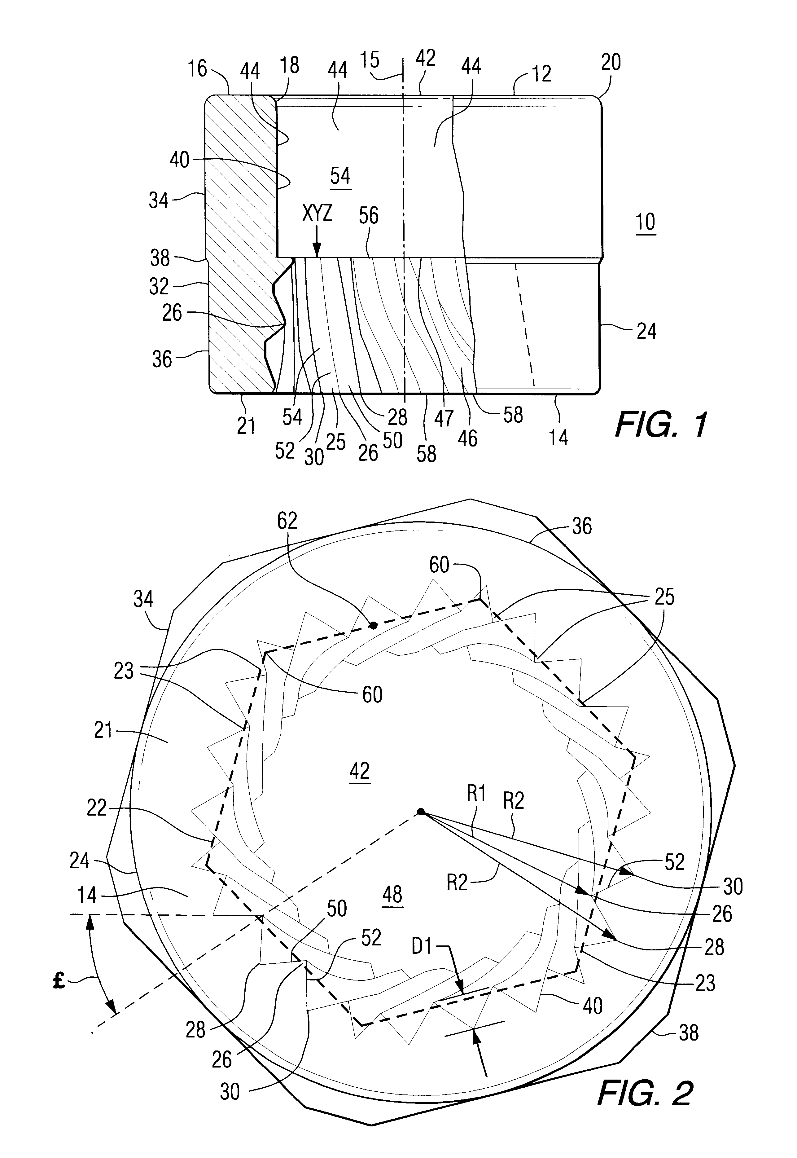
As shown in FIGS. 1 and 2, the presently disclosed tool 10 is used for the removal of nuts and other threaded fasteners from their corresponding bolts or equivalent threaded members. In particular, tool 10 is useful in the removal of threaded fasteners that have been damaged or corroded such that the outer surface of the fastener has been damaged and the fastener cannot be readily removed by wrenches, sockets or other tools that are designed for the removal of fasteners that are in good condition.

Tool 10 includes a first end 12 and a second end 14 that are aligned on a longitudinal center axis 15. First end 12 is in the general shape of a planar ring 16 that has a square inner edge 18 and a hexagonal outer edge 20. Second end 14 is in the general shape of a planar ring 21 that has a generally hexagonal inner edge 22 that includes hexagonal sides 23. Second end 14 further includes a circular outer edge 24. While inner edge 22 is hexagonal in the example of the preferred embodiment, i...


PUM


Abstract

A tool for removing damaged fasteners and a method for making such tool wherein the tool (10) includes a first end (12) and a second end (14) with an outside surface (32) and an inside surface (40) defined between ends (12) and (14). A portion (46) of inside surface (40) is in the shape of an hexagonal frustum (54) that has a major end (58) and that includes spiral splines (25). Splines (25) have constant depth between the major end (58) and the minor end (56) of frustum (54) and the relief angle (£) of splines (25) decreases in the direction from minor end (56) toward major end (58). In the method for making the tool (10), a tubular section (118) is made from a tapered blank (91) by piercing one end of the tapered blank with a pierce punch (132). One end of the tubular section is then driven onto a splined punch (162) to provide splines in one end of the tubular section. The tubular section is then stripped off of the punch (162) by a kick-out sleeve (166) and extruded through a round-to-hexagonal extrusion insert (182) to provide portion (46) of the inner surface (40) with a tapered, hexagonal shape.

Description

1. Field of the InventionThe presently disclosed invention relates to tools for removing threaded fasteners and, more particularly, fasteners wherein the perimeter surface of the fastener has been damaged by corrosion or mechanical stress such that the corners of the polygonal surface have become rounded.2. Description of the Prior ArtMany types of threaded fasteners are known in the prior art. Such fasteners have various designs for cooperation of the fastener with a threaded member. Some of these fasteners, such as wing nuts or thumb screws, are intended to be applied and removed without the use of tools. Other fasteners, such a threaded nuts, require the use of tools for their application and removal.In particular, many types of fasteners have an inner threaded surface and an outer polygonal surface, typically a hexagonal surface. The inner threaded surface cooperates with the threaded member and the outer surface cooperates with a tool that is used to apply or remove the fastene...

Claims


Application Information

Patent Timeline
IPC IPC(8): B21K5/16B21K21/08B21K21/00B25B13/06B21K5/00B25B13/00B25B27/14B25B27/18
CPCB21K5/16B25B27/18B25B13/065B21K21/08
Inventor JORDAN, CHALMER C.
Owner JORDAN CHALMER C
Learn More