Full-airspace-covering beamforming phased array antenna (PAA)

A beamforming and beamforming technology, applied in the directions of antennas, antenna arrays, electrical components, etc., can solve the problems of high power consumption, high cost, and large number of R components, so as to reduce the number of use, reduce complexity and cost, The effect of small far-field phase fluctuations

Inactive Publication Date: 2013-04-03
BEIJING RES INST OF TELEMETRY +1
View PDF2 Cites 36 Cited by
  • Summary
  • Abstract
  • Description
  • Claims
  • Application Information

AI Technical Summary

Problems solved by technology

However, the disadvantage of this implementation is that two-dimensional scanning requires a large number of radiation units, and each radiation unit needs to be equipped with a corresponding ...

Method used


Image

  • Full-airspace-covering beamforming phased array antenna (PAA)
  • Full-airspace-covering beamforming phased array antenna (PAA)
  • Full-airspace-covering beamforming phased array antenna (PAA)

Examples


Embodiment Construction

[0026] The present invention will be further described below in conjunction with accompanying drawing.

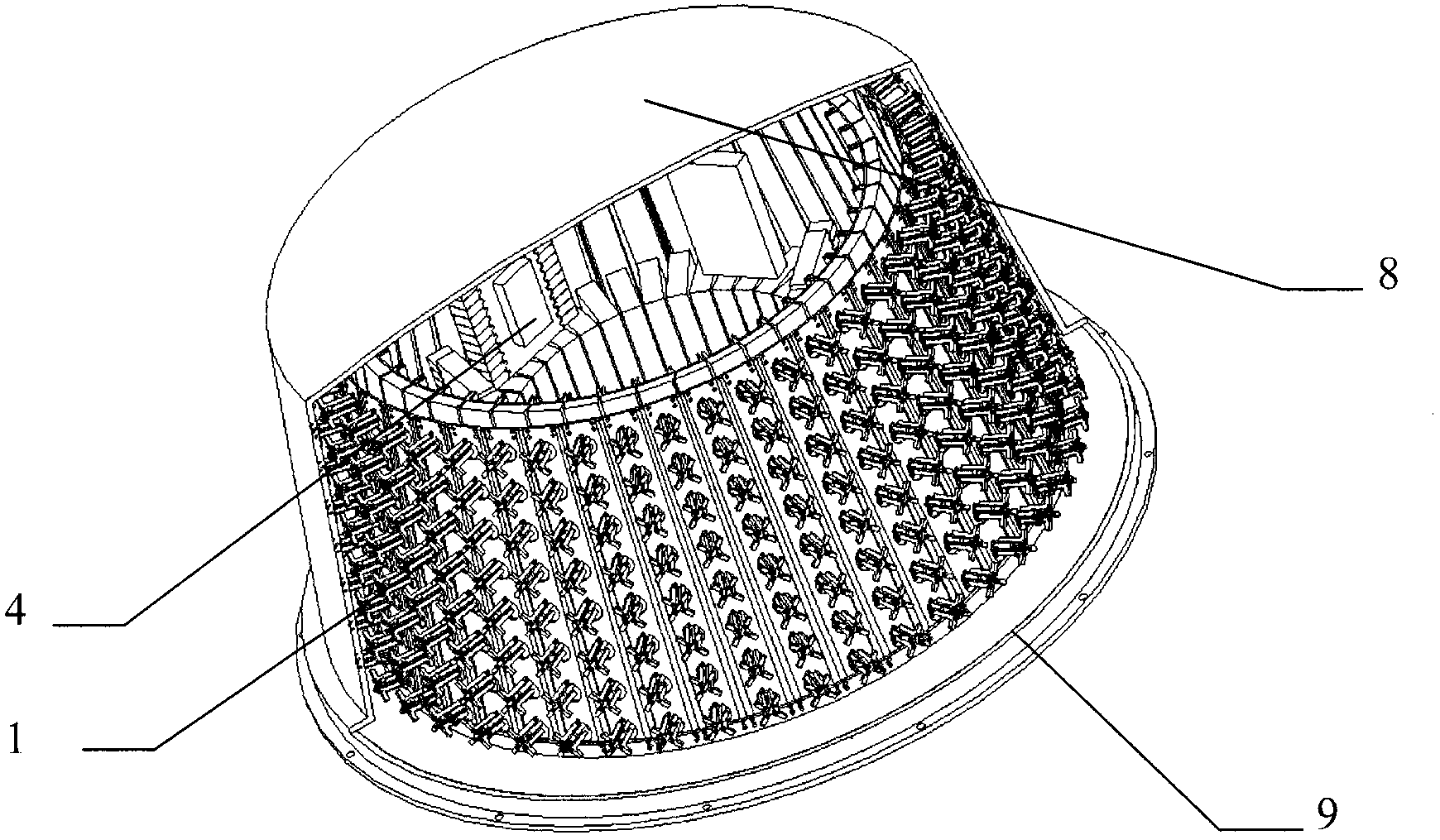
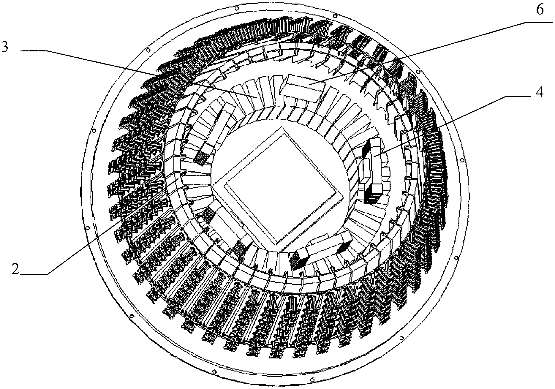
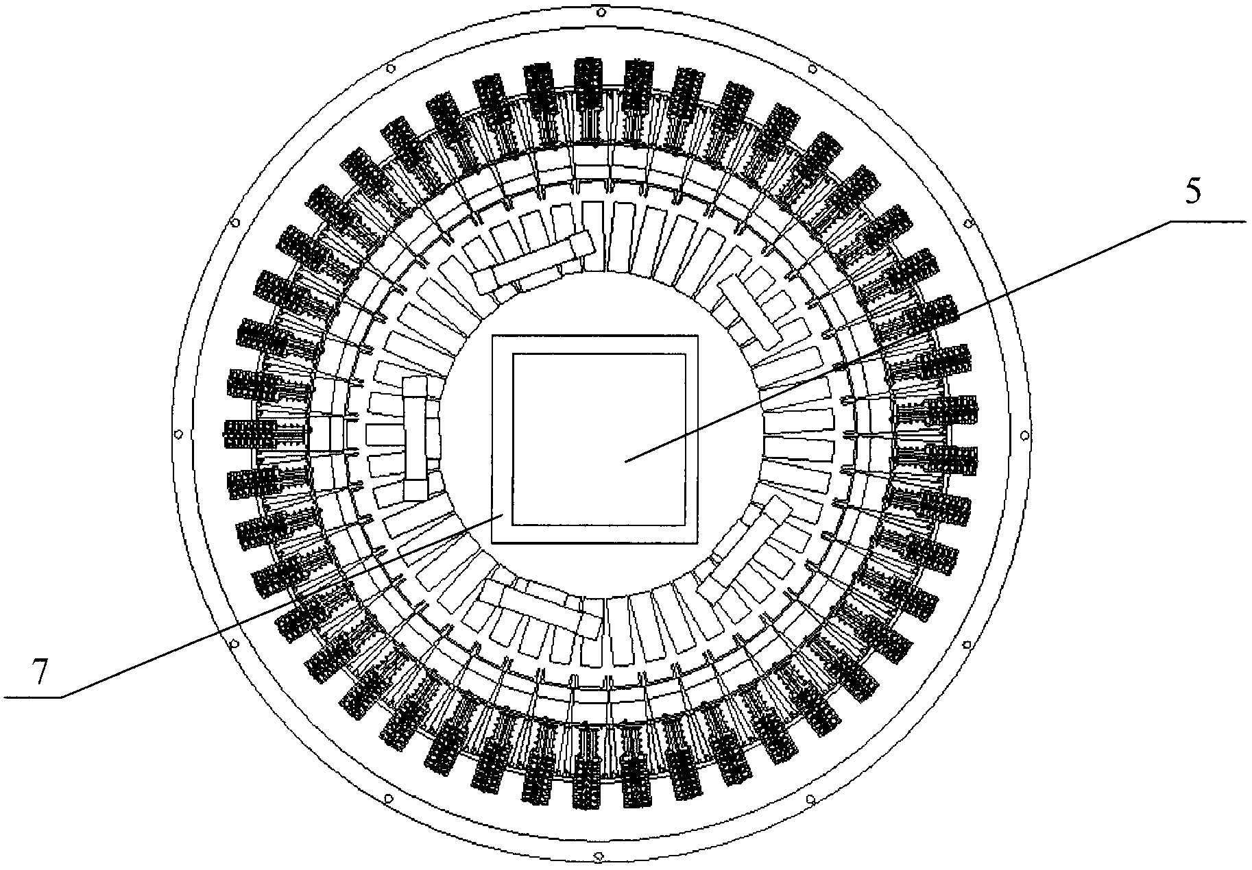
[0027] Such as figure 1 , 2 , 3, and 4, the full airspace coverage beamforming phased array antenna of the present invention includes a passive antenna array 1, a beamforming network 2, an R component 3, a beamforming network 4, a beam controller 5, and a calibration network 6 and secondary power supply 7; there is a radome 8 made of wave-transparent material outside the antenna to avoid possible damage to the antenna in various harsh environments; all parts are installed on the support structure 9, integrated design .

[0028] The passive antenna front 1 adopts a conical frustum array, and the array element can be in the form of an array antenna, a microstrip antenna, etc., and an array antenna is used in this embodiment. The array element is in the column direction along the direction of the cone generatrix, and each column contains N 0 units, arranged at intervals d ...


PUM


Abstract

The invention discloses a full-airspace-covering beamforming PAA for aircraft target tracking and measurement and control. The PAA comprises a passive array surface (1), a beam forming network, a beam controller (5), a calibration network (6), a secondary power supply (7) and a support structure (9), wherein the passive array surface (1) is composed of a plurality of antenna array elements; the beam forming network is formed by a beamforming network (2), an R assembly (3) and a beam synthetic network (4); the beam controller (5) is used for generating beam-controlled codes, the calibration network (6) is used for calibrating each access amplitude, the secondary power supply (7) is used for supplying power for an active circuit, and the support structure (9) is used for installation and fixation. According to the PAA, a one-dimensional forming and one-dimensional cone frustum PAA scanning mode is adopted, cosecant square beams with the highest gains horizontally are formed in the array direction through the beamforming network, coverage ranging from 0 degree to 90 degrees in the pitching direction is achieved, coverage at 360 degrees is achieved circumferentially through phased array beam scanning, and independent multiple beams are formed through multi-channel phase shift and beam synthesis to solve the multi-target tracking problem.

Description

technical field [0001] The invention belongs to the field of aircraft target tracking and measurement and control, and particularly relates to a receiving antenna that needs to cover an airspace range with an elevation angle of 0° to 90° and an azimuth of 360°, and realize simultaneous multi-target tracking. Background technique [0002] When performing multi-target tracking and measurement and control of aircraft, the receiving antenna of the ground measurement and control station needs multiple independent high-gain beams to cover the airspace range of elevation angle 0°-90° and azimuth 360° at the same time, that is, hemispherical coverage. Using azimuth and elevation two-dimensional scanning phased array is the most natural way to realize it, but the general maximum scanning angle of ordinary planar two-dimensional scanning phased array antenna does not exceed ±60°, so multi-plane surfaces (pyramids) or curved surfaces must be conformal array. However, the disadvantage ...

Claims


Application Information

Patent Timeline
IPC IPC(8): H01Q21/00H01Q3/30
Inventor 肖伟清孙向珍郭恒刘昊
Owner BEIJING RES INST OF TELEMETRY
Why Eureka
Try Eureka