Method of repairing composite material and composite material

a composite material and repair method technology, applied in the direction of thin material handling, aircraft maintenance, lamination ancillary operations, etc., can solve the problems of time and labor, structural body disassembly, and repair becomes necessary,

Active Publication Date: 2014-05-22
MITSUBISHI AIRCRAFT
View PDF5 Cites 35 Cited by
  • Summary
  • Abstract
  • Description
  • Claims
  • Application Information

AI Technical Summary

Benefits of technology

[0032]According to the repair method of the invention, a practical repair method by approaching from one side in the case in which damage extends across the entire thickness of a composite material can be provided.
[0033]The composite material of the invention also can benefit from similar advantages.

Problems solved by technology

Incidentally, when the skin is damaged due to undergoing an impact, repair becomes necessary.
However, if it is not possible for the worker to enter the boxed space, the structural body has to be disassembled.
There is, however, such a problem with this method that it takes time and labor to form an oval-shaped through hole.
Furthermore, since an investigation on the strength of repair parts in each product in order to determine the orientation of the oval hole, it takes time until beginning the repair work.
For these reasons, it is difficult to adopt the method of forming an oval-shaped through hole.
Since there are the support members, fuel tanks, various devices and the like in the wings and fuselage, it is difficult to repair a skin from the inside.

Method used


Image

  • Method of repairing composite material and composite material
  • Method of repairing composite material and composite material
  • Method of repairing composite material and composite material

Examples


first embodiment

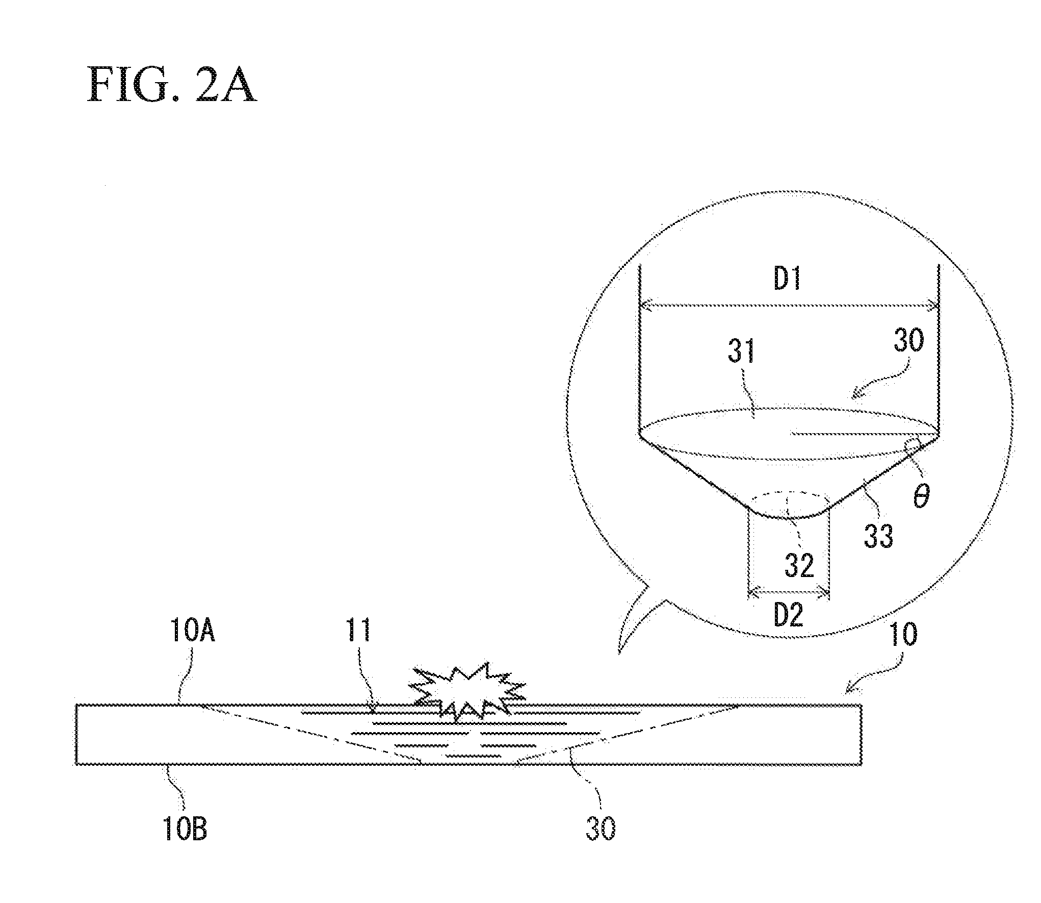
[0040]An explanation will be given as to a method of repairing a damaged composite material by approaching from one side (the front side) and a repaired composite material.

[0041]A composite material 10 to be repaired is composed of laminated plural sheets of CFRP. It is possible to use fiber reinforced plastics such as GFRP (Glass Fiber Reinforced Plastics) or the like instead of the CFRP.

[0042]This composite material 10 forms a skin serving as the outer face of main wings and tail unit of an aircraft, and constructs a structural body by being assembled together with spars and ribs.

[0043]The repair is carried out without disassembling the structural body.

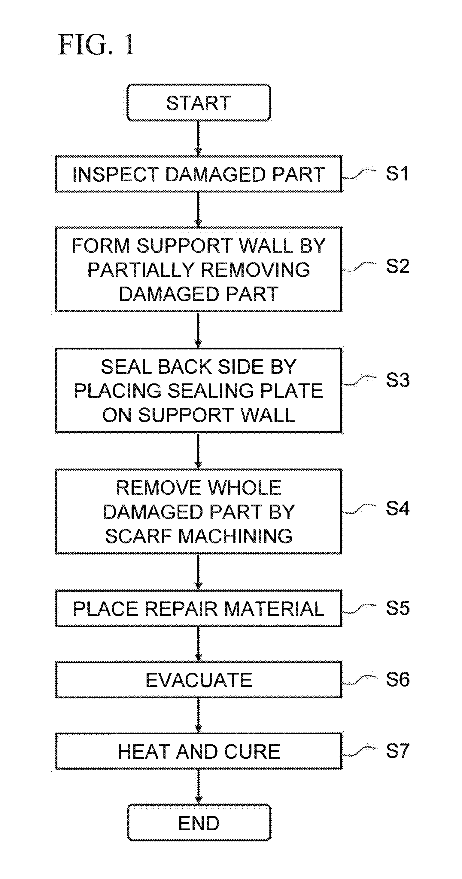
[0044]First, a damaged part 11 of the composite material 10 is subjected to an ultrasonic inspection (step S1) as shown in FIG. 1. The ultrasonic inspection can be carried out from the front side 10A of the composite material 10 (from the outside of the box) by use of a known device and method.

[0045]There are plural places suffered ...

second embodiment

[0074]Next, the second embodiment of the present invention will be described with reference to FIGS. 5A and 5B.

[0075]In the second embodiment, an explanation will be given mainly as to the difference as compared with the first embodiment, and elements identical to those of the first embodiment are indicated by identical reference characters, and repeated descriptions are omitted.

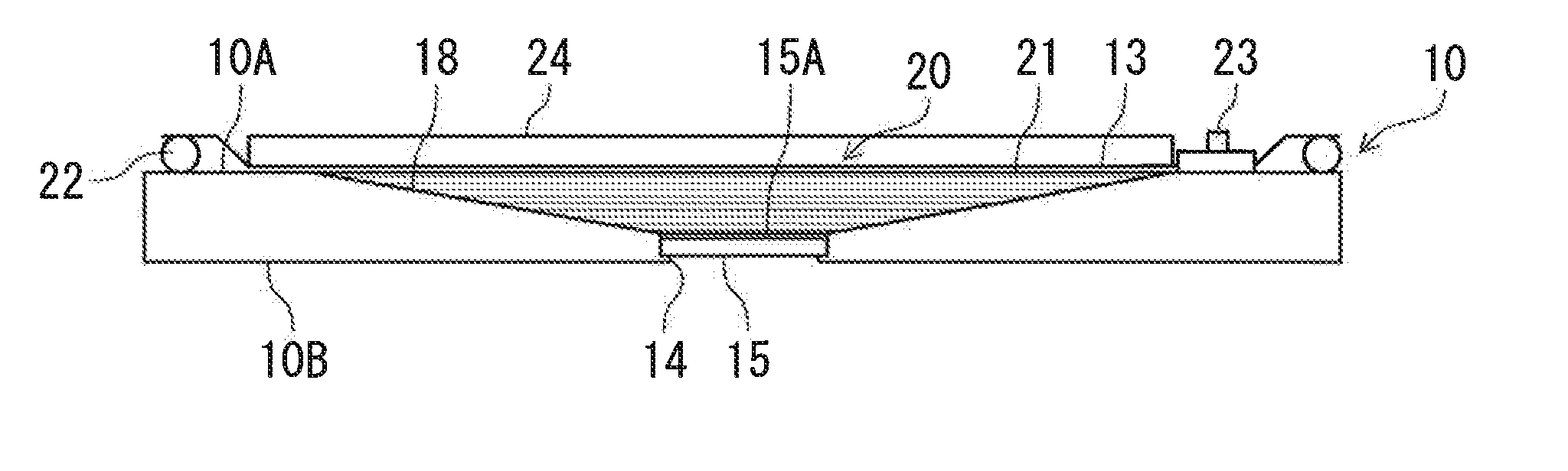
[0076]As shown in FIG. 5A, a sealing plate 15 has a sealing plate slope 151 formed to be inclined with respect to a back side 10B, and a support wall 14 has a support wall slope 141 formed by following the sealing plate slope 151 in this embodiment.

[0077]A through concave portion 13 of this embodiment is configured of a concave portion slope 18 denoted as the first slope, and the support wall slope 141 denoted as the second slope.

[0078]The support wall slope 141 is a chamfered edge that follows the sealing plate slope 151. The diameter of the sealing plate slope 151 is enlarged from the back side 10B of the ...


PUM

PropertyMeasurementUnit
diameteraaaaaaaaaa
thicknessaaaaaaaaaa
distanceaaaaaaaaaa

Abstract

A method of repairing a composite material is provided in which a frustum-shaped portion of a composite material is removed, and the composite material and a repair material are bonded with each other while evacuating. The repair method includes step S2 of removing a damaged part 11 from the front side so as to pass through in the thickness direction while leaving a support wall protruding inward in the radial direction from the periphery of the top face of the frustum-shaped portion; step S3 of sealing the back side by placing a sealing plate, which is inserted from the front side into a through hole formed by the removing step, on the support wall; step S5 of placing the repair material through an adhesive on the composite material where the frustum-shaped portion has been removed; and step S6 of evacuating in a state in which the front side is sealed.

Description

BACKGROUND[0001]1. Technical Field[0002]The present invention relates to a method of repairing a composite material, and also to a composite material having been repaired.[0003]2. Related Art[0004]As a skin forming the outer face of an aircraft wing, a composite material that is composed of laminated plural sheets of CFRP (Carbon Fiber Reinforced Plastics) or the like has been used.[0005]The skin is arranged on the front and back sides of the wing with a distance therebetween, and is constructed in a box shape together with spars that form the front and rear edges of the wing, respectively. The boxed space is provided with ribs for supporting the skin on the front and back sides, and is utilized for housing various devices and fuel.[0006]Incidentally, when the skin is damaged due to undergoing an impact, repair becomes necessary. The repair is made in a manner in which the damaged part suffered laminate exfoliation due to the impact is removed, and a concave portion formed by removi...

Claims


Application Information

Patent Timeline
Patent Type & Authority Applications(United States)
IPC IPC(8): B29C73/24B64C3/26
CPCB29C73/06B29C73/10B29C73/26B29C2073/264B29C2073/268B64F5/40Y10T428/20B64C3/26B32B37/1009B32B38/10
Inventor SHIGETOMI, TOSHIKAZUSUHARA, MASAYOSHIISHIDA, MORIMASAMUTO, SHUHEI
Owner MITSUBISHI AIRCRAFT
Why Eureka
Try Eureka