
Intermediate disk for a motor vehicle

Inactive Publication Date: 2002-03-05
ZF FRIEDRICHSHAFEN AG
View PDF11 Cites 27 Cited by
  • Summary
  • Abstract
  • Description
  • Claims
  • Application Information

AI Technical Summary

Benefits of technology

As a result of this construction, the recesses are freely accessible from the sides of each disk part remote from the friction surfaces, so that they can easily be incorporated in the disk parts or provided during casting. Since the intermediate disk does not require any machining proceeding from its edge to produce the recesses, it is very simple and economical to produce. In addition, the disk parts require only the thickness necessary for a given stability of the intermediate disk. The quantity and dimensions of the spacers are arrangeable so that the intermediate disk is constructed with high stability. Accordingly, small and thin intermediate disks for multiple disk clutches used in passenger vehicles are provided with recesses according to the invention to increase their heat-releasing surface.
According to another embodiment of the present invention, the carrying off of heat through the recesses is improved in that the spacers are constructed as air-conducting elements for guiding the air present between the disk parts.

Problems solved by technology

This frictional heat produces a very intensive heating of the intermediate disk, so that a reliable frictional engagement of the clutch is no longer guaranteed.
However, for technical reasons related to casting, it is usually not possible, particularly in small clutches such as those for passenger vehicles, to employ casting to provide the recesses in the intermediate disks which are generally very thin.
However, this type of construction of the intermediate disk is very cost-intensive.

Method used


Image

  • Intermediate disk for a motor vehicle
  • Intermediate disk for a motor vehicle
  • Intermediate disk for a motor vehicle

Examples


Embodiment Construction

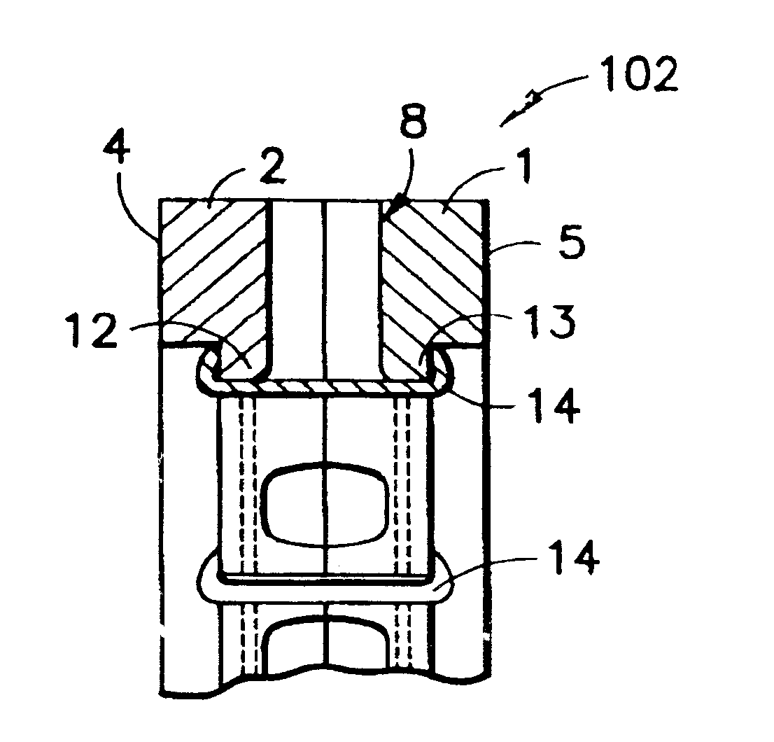
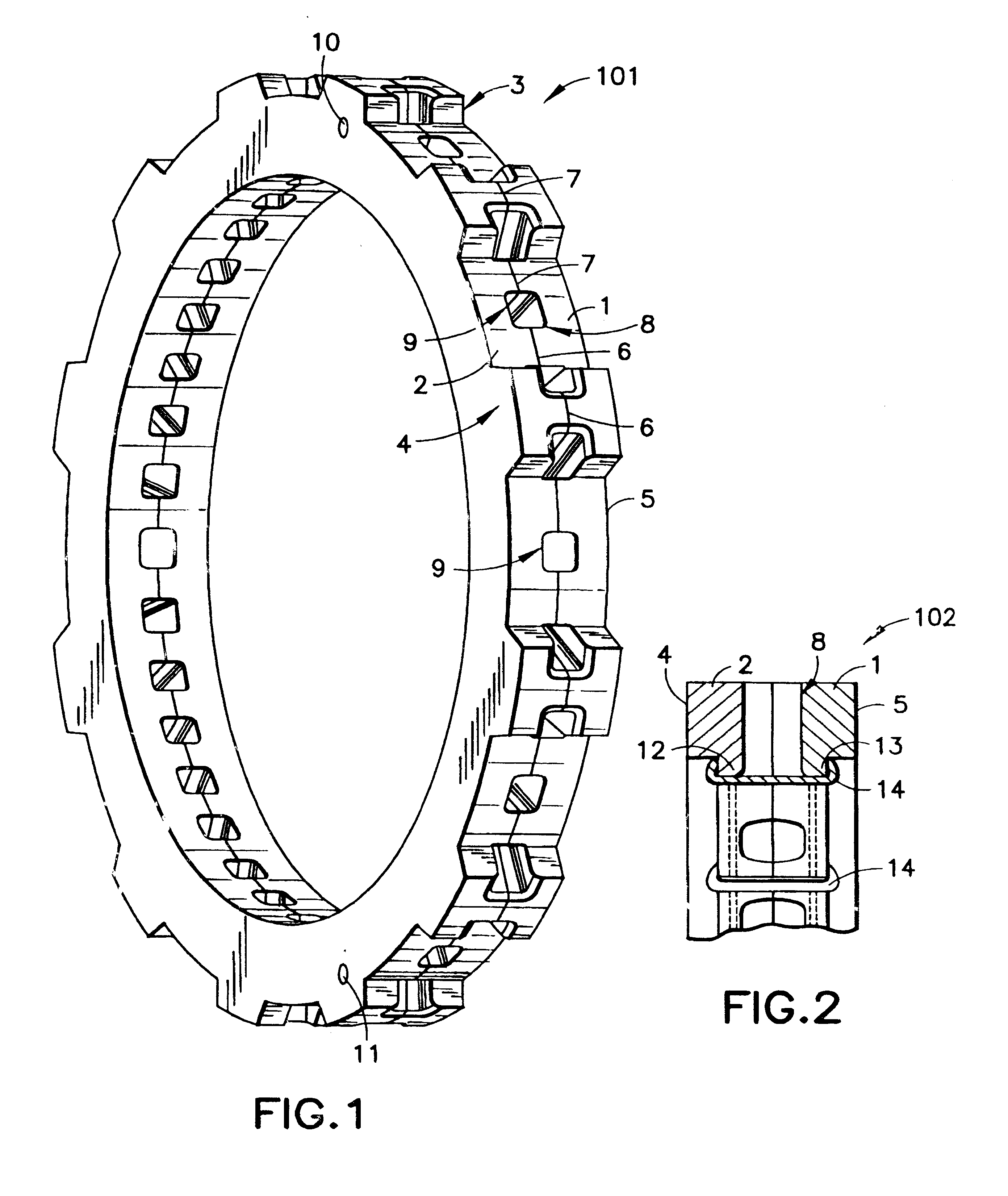
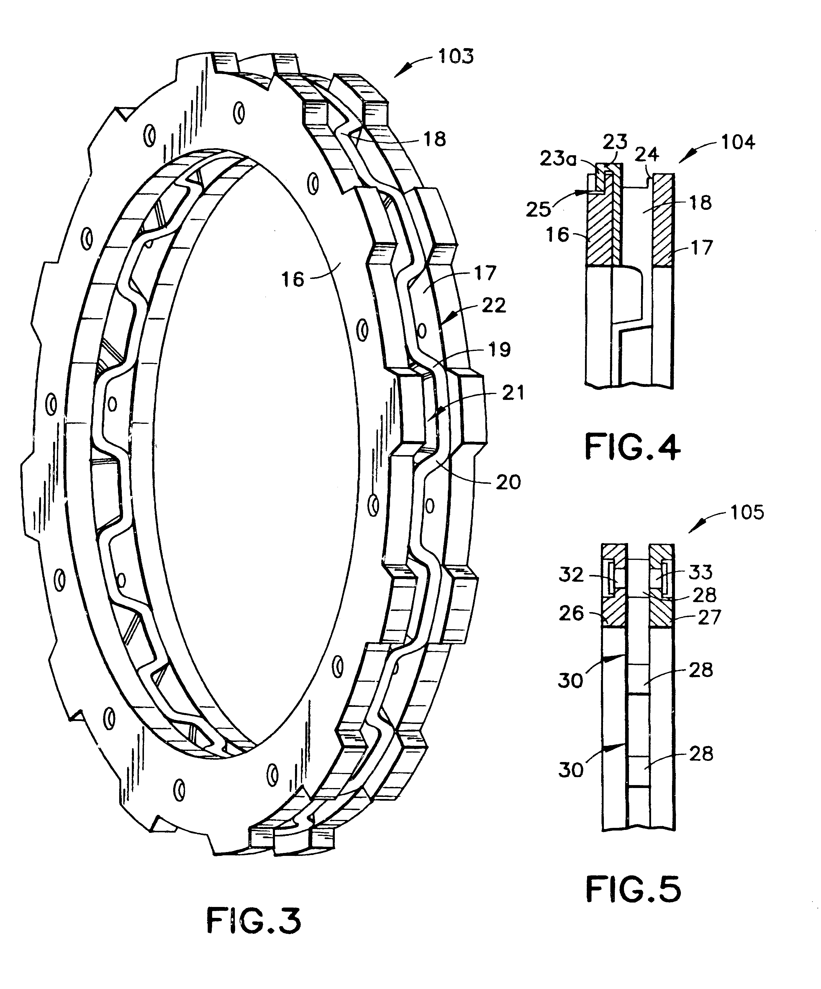
FIG. 1 shows an intermediate disk 101 according to the present invention with first and second disk parts 1, 2 (collectively referred to as disk parts 1, 2). The intermediate disk 101 has a toothing 3 facing radially outward. The intermediate disk 101 may be connected with a first shaft of the clutch (not shown) via the toothing 3 so that the intermediate disk 101 is fixed with respect to rotation and axially displaceable relative to the first shaft such, for example, as via an input part (not shown). The disk parts 1, 2 have respective first and second friction surfaces 4, 5. The first disk part 1 includes first spacers 6 which project toward the second disk part 2 and the second disk part 2 has second spacers 7 which project toward the first disk part 1. The disk parts 1,2 contact one another via the first and second spacers 6, 7. The disk parts 1, 2 are manufactured integral with the first and second spacers 6, 7. The first and second spacers 6, 7 respectively form recesses 8, 9 ...


PUM


Abstract

An intermediate disk for a motor vehicle clutch with friction surfaces on both sides includes two disk parts. On the sides of the disk parts remote of the friction surfaces, the disk parts have spacers which laterally define recesses between the disk parts. This arrangement of the intermediate disk provides a large heat-releasing surface even when the intermediate disk has small dimensions.

Description

1. Field of the InventionThe present invention relates to an intermediate disk for a motor vehicle clutch having friction surfaces on both sides and fastened for rotation with a first shaft, said intermediate disk being arranged between friction facings which are fastened for rotation with a second shaft for generating a frictional engagement between the friction facings and the friction surfaces, and the intermediate disk having recesses in a central area between the friction surfaces.2. Description of the Related ArtIntermediate disks are used in modern multidisk clutches and are known from practice. The prior art intermediate disk is manufactured, for instance, as a cast part and recesses between the friction surfaces are formed by cores which are to be inserted in the casting mold and guided from the edge of the intermediate disk toward its center. When the clutch is operated, and especially during an engagement process, frictional heat is generated at the friction surfaces when...

Claims


Application Information

Patent Timeline
IPC IPC(8): F16D13/58F16D13/72F16D13/64
CPCF16D13/72F16D13/64F16D13/70F16D2300/0212
Inventor ORLAMUNDER, ANDREASLINK, ACHIM
Owner ZF FRIEDRICHSHAFEN AG
Learn More