Ergonomic controls for a personal computer CPU
a technology of ergonomic control and computer chassis, which is applied in the direction of portable computer details, electric apparatus casings/cabinets/drawers, instruments, etc., can solve the problems of launch interface software, lack of design and ergonomic control that make personal computers completely suitable for home use, and box-like appearance of personal computers used in the hom
- Summary
- Abstract
- Description
- Claims
- Application Information
AI Technical Summary
Problems solved by technology
Method used
Image
Examples
first embodiment
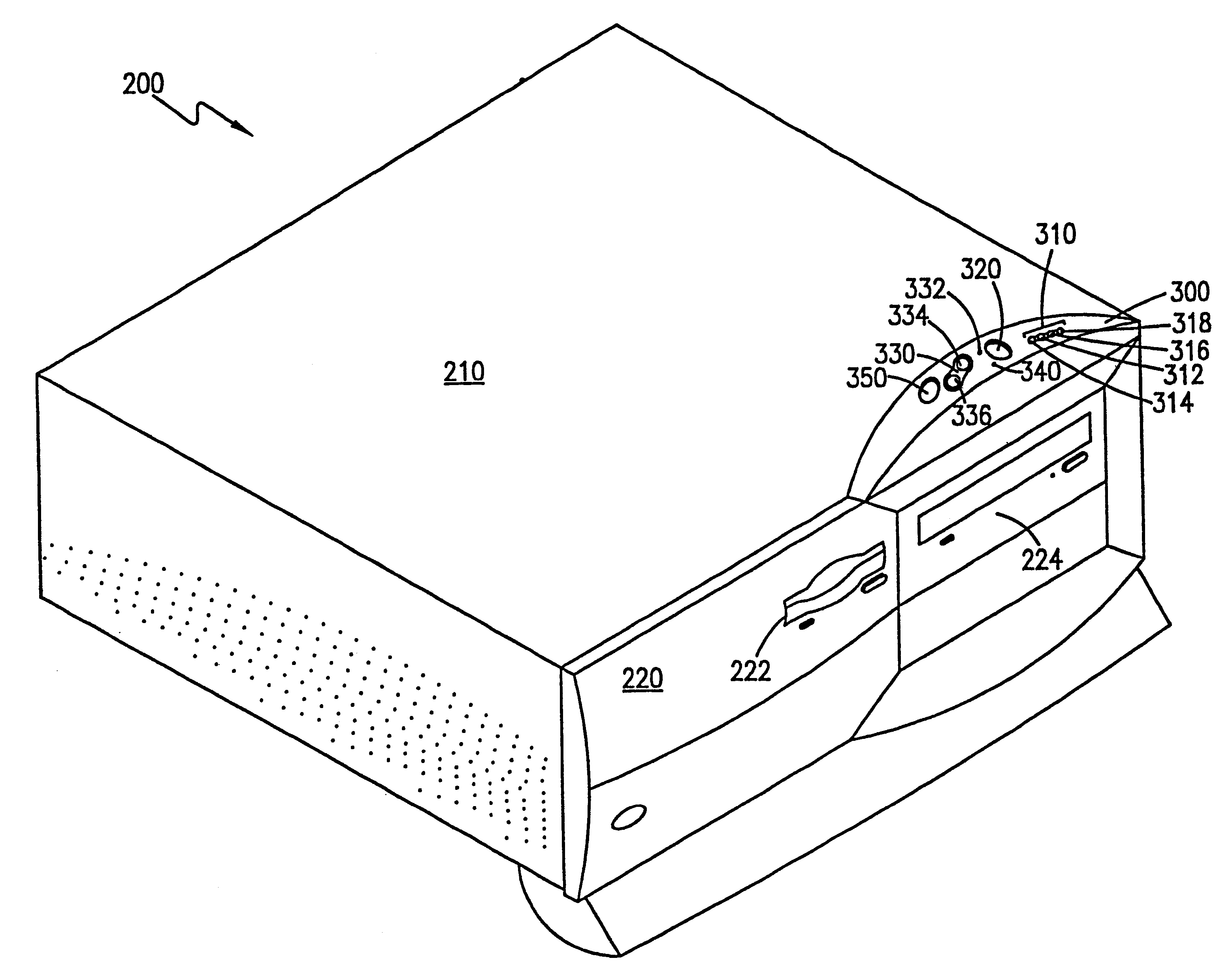
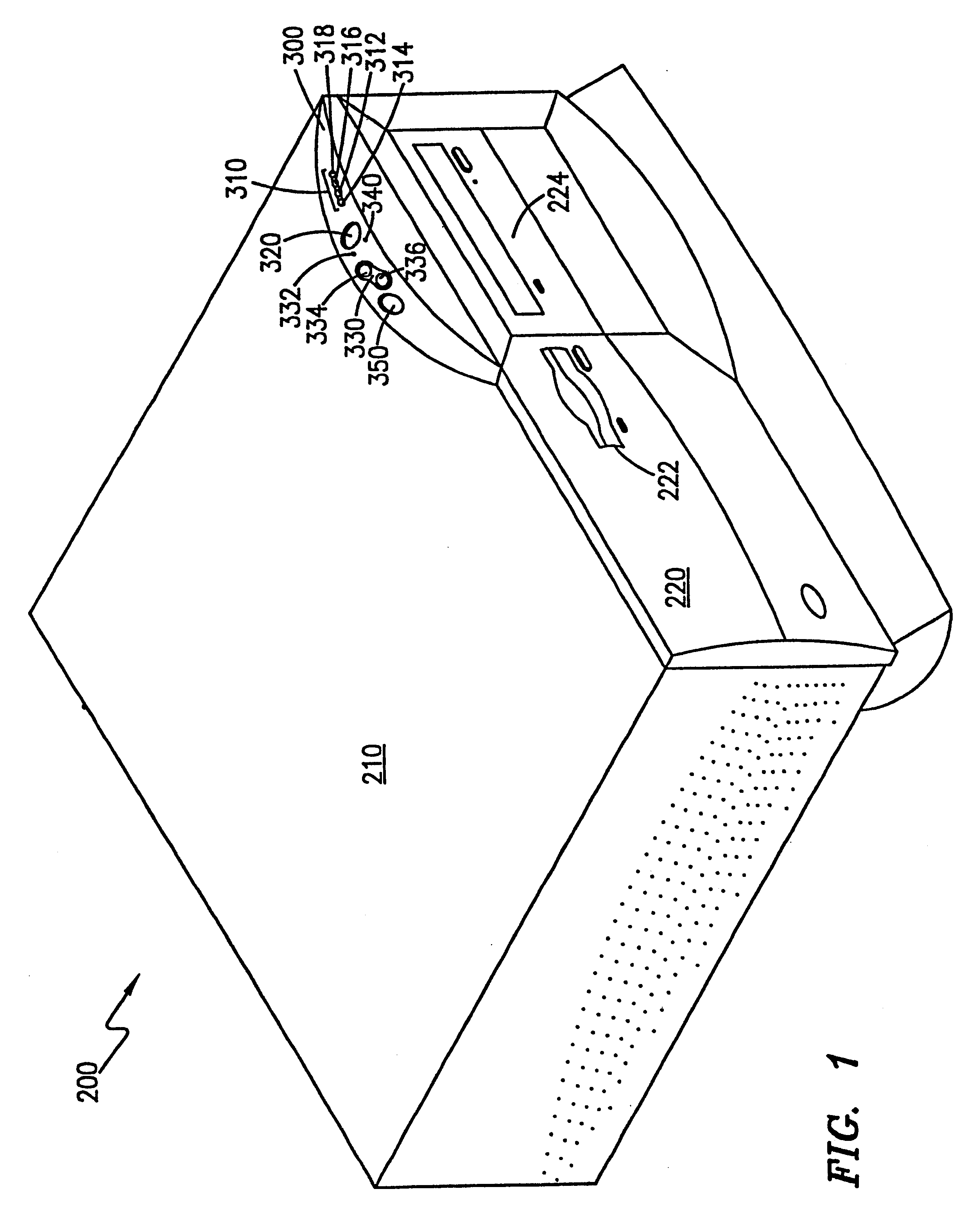
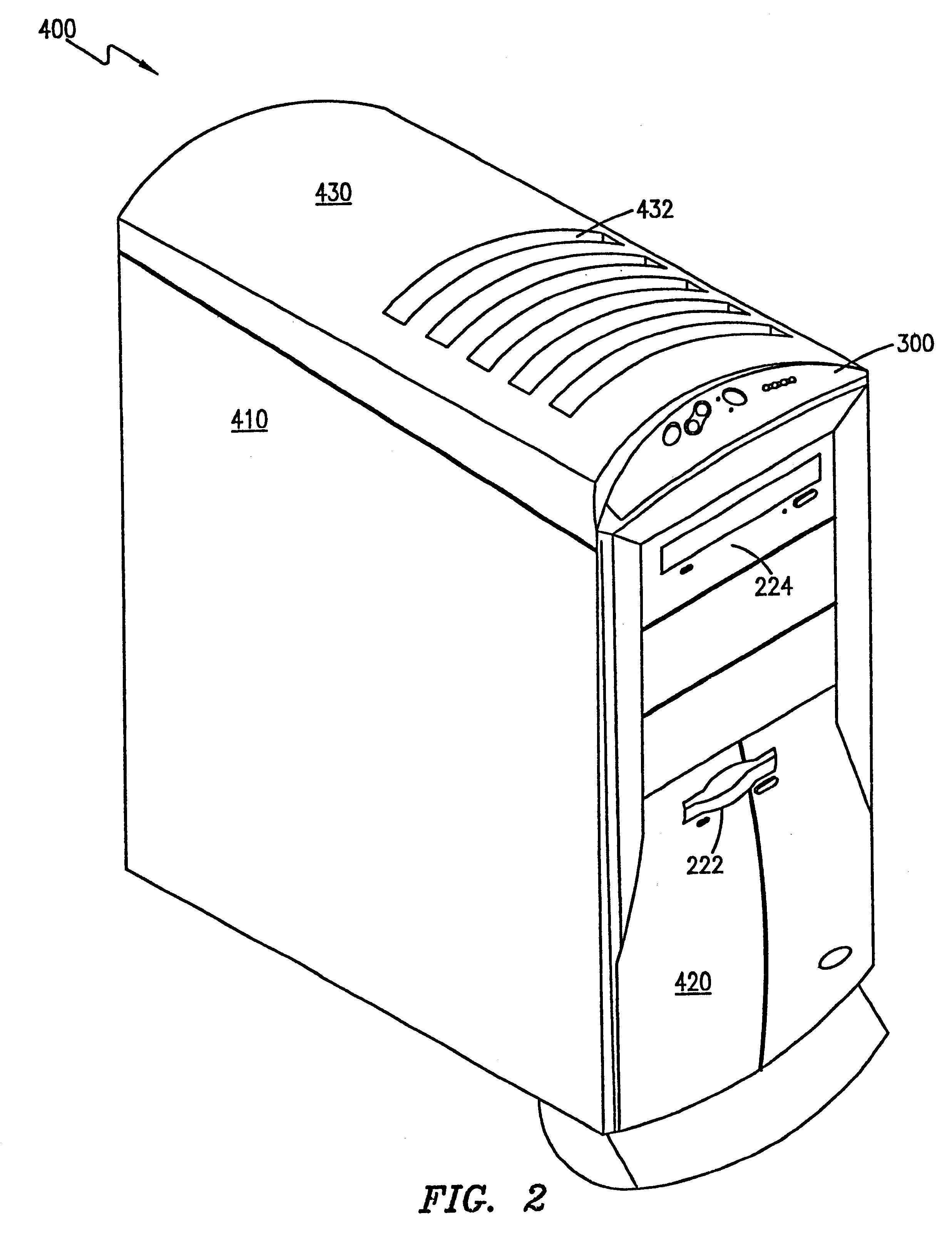
Referring first to FIG. 1, there is shown a perspective view of the present invention, a desktop CPU 200. This embodiment includes a chassis body 210 with an attached chassis face 220. The chassis face is comprised of several user interfaces such as floppy disk drive access and controls 222 and CD-ROM drive access and controls 224. Further included on the chassis face 220 is an ergonomic control panel 300. The ergonomic control panel 300 is preferably offset at an angle from the vertical plane of the chassis face 220 in order to facilitate ease of access and use.
embodiment 200
Still referring to FIG. 1, the ergonomic control panel 300 includes audio compact disc (CD) controls 310. These controls 310 can be any means used to manipulate the play of an audio CD in the CD-ROM drive 224. In the present embodiment 200, these controls include a play / pause button 312, a stop button 314, a track advance button 316, and a track reverse button 318. Other controls found in a typical CD player could also be included, such as an eject button, a "fast-forward" button, a "rewind" button, and the like. The audio CD controls 310 are connected to the CD-ROM drive 224 by a means which allows the input signals to be sent directly to the CD-ROM drive control circuitry. It is further understood that control buttons for a tape drive or other storage media devices could be incorporated into the ergonomic control panel 300.
Referring still to FIG. 1, the ergonomic control panel 300 also includes a sleep function control means 320. In the present embodiment 200, this means is a butt...
embodiment 500
Still referring to FIG. 3, the ergonomic control panel 600 in the present embodiment 500 also includes volume control means 680 to control the audio output of the speakers 544. The volume control means 680 include a volume increase button 682, a volume decrease button 684, and a volume mute button 686. Controls could also be added for other audio output manipulation, such as bass and treble level, balance control, and other such functions found on a typical stereo system. Also, although shown as buttons, these volume control means could also include knobs, switches, slides, or other consumer electronic control devices. The control panel 600 is further comprised of a set of monitor controls 690 for manipulation of the video output of the monitor. The controls 690 are preferably "pop-out" knobs so that while not in use, they can be inserted into and flush with the control panel 600.
PUM
 Abstract
Description
Claims
Application Information
 - R&D
- Intellectual Property
- Life Sciences
- Materials
- Tech Scout
- Unparalleled Data Quality
- Higher Quality Content
- 60% Fewer Hallucinations
Browse by: Latest US Patents, China's latest patents, Technical Efficacy Thesaurus, Application Domain, Technology Topic, Popular Technical Reports.
© 2025 PatSnap. All rights reserved.Legal|Privacy policy|Modern Slavery Act Transparency Statement|Sitemap|About US| Contact US: help@patsnap.com


