

Composite deck
a composite roof and floor decking technology, applied in the field of composite roofs and floor deck assemblies, can solve the problems of rodents and insects traveling within the ribs, the ribs are open-ended and provide little barrier for soundproofing, and the concrete slab is more likely to be sheared with the metal decking
- Summary
- Abstract
- Description
- Claims
- Application Information
AI Technical Summary
Benefits of technology
Problems solved by technology
Method used
Image

Examples
Embodiment Construction
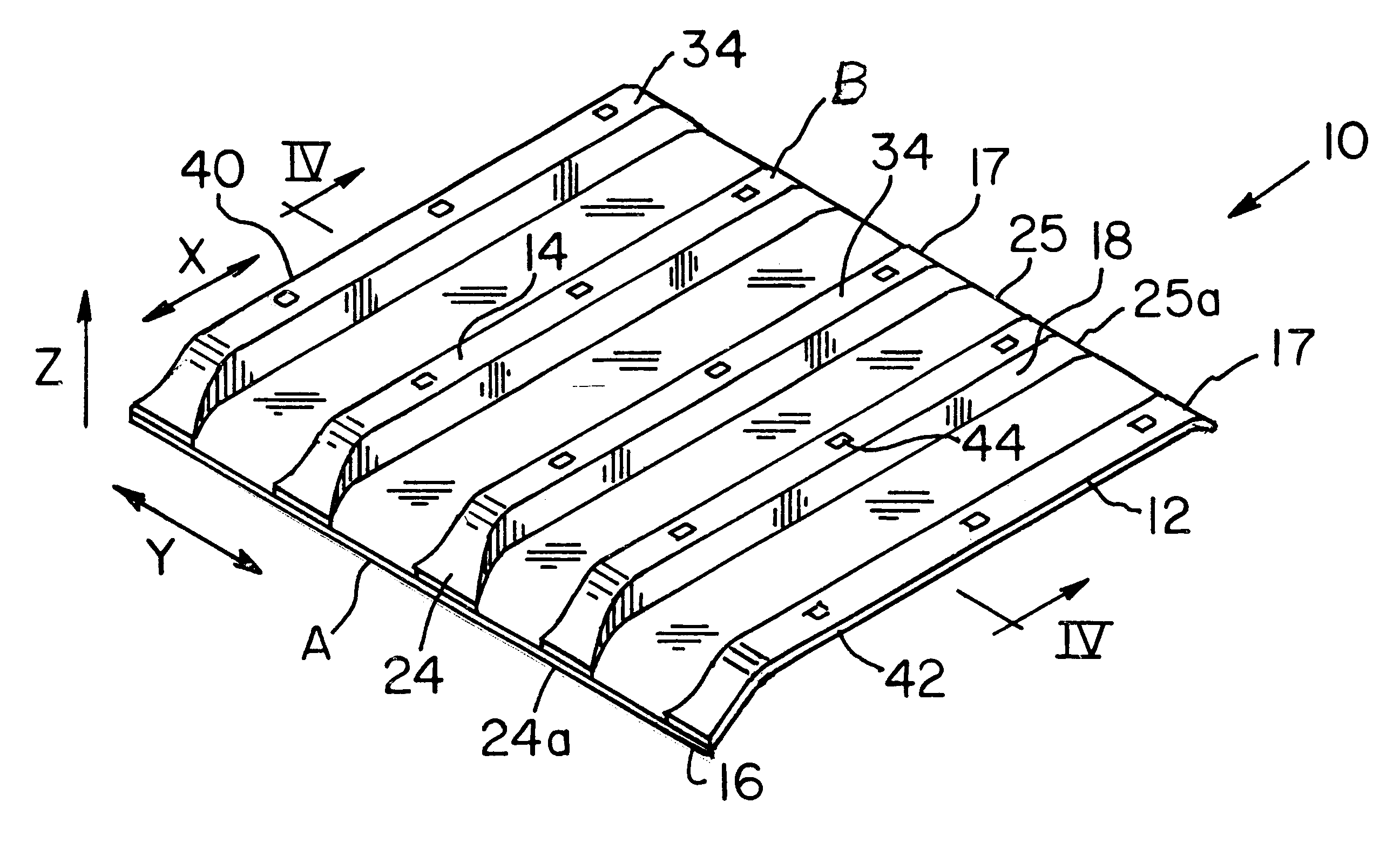
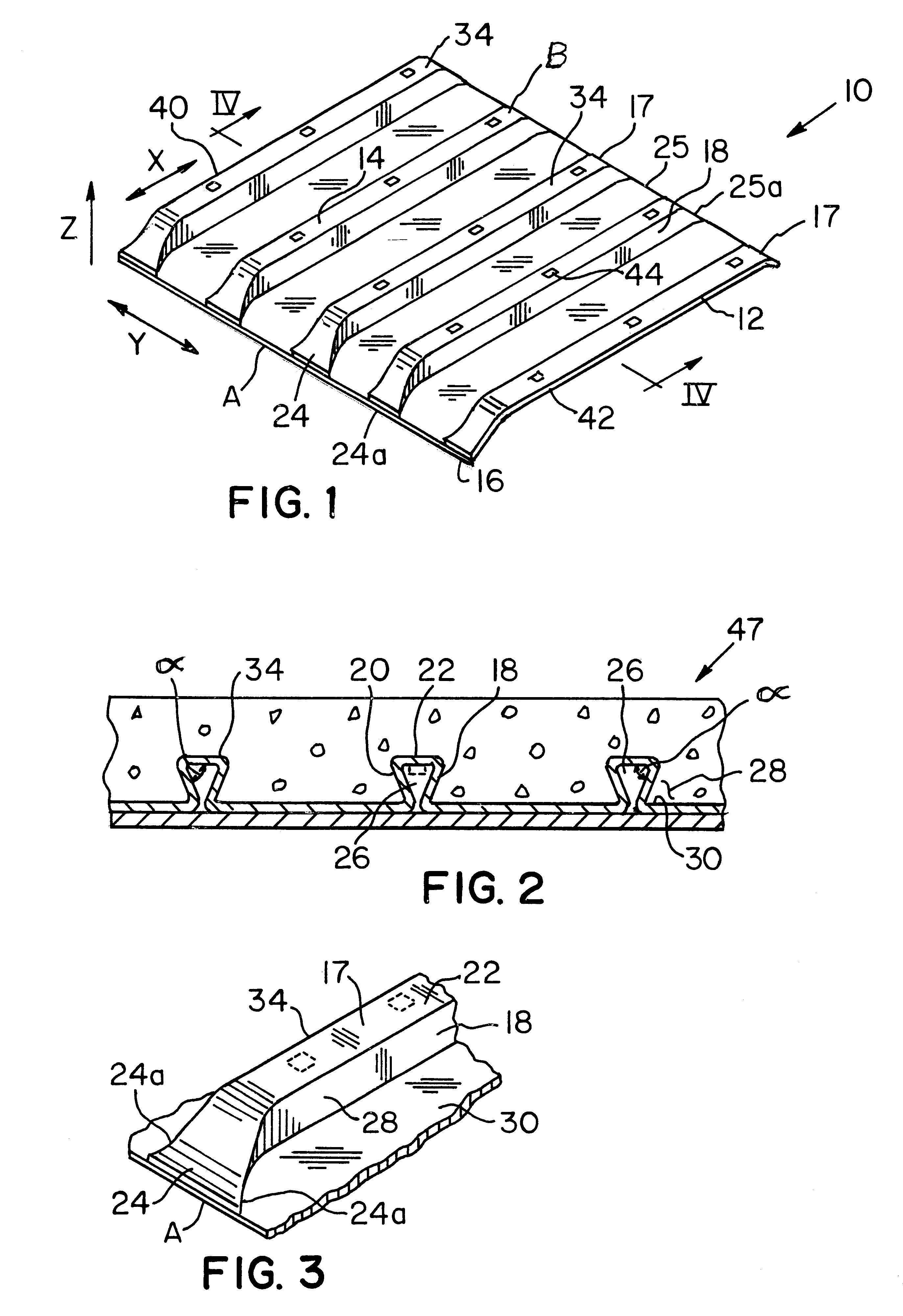
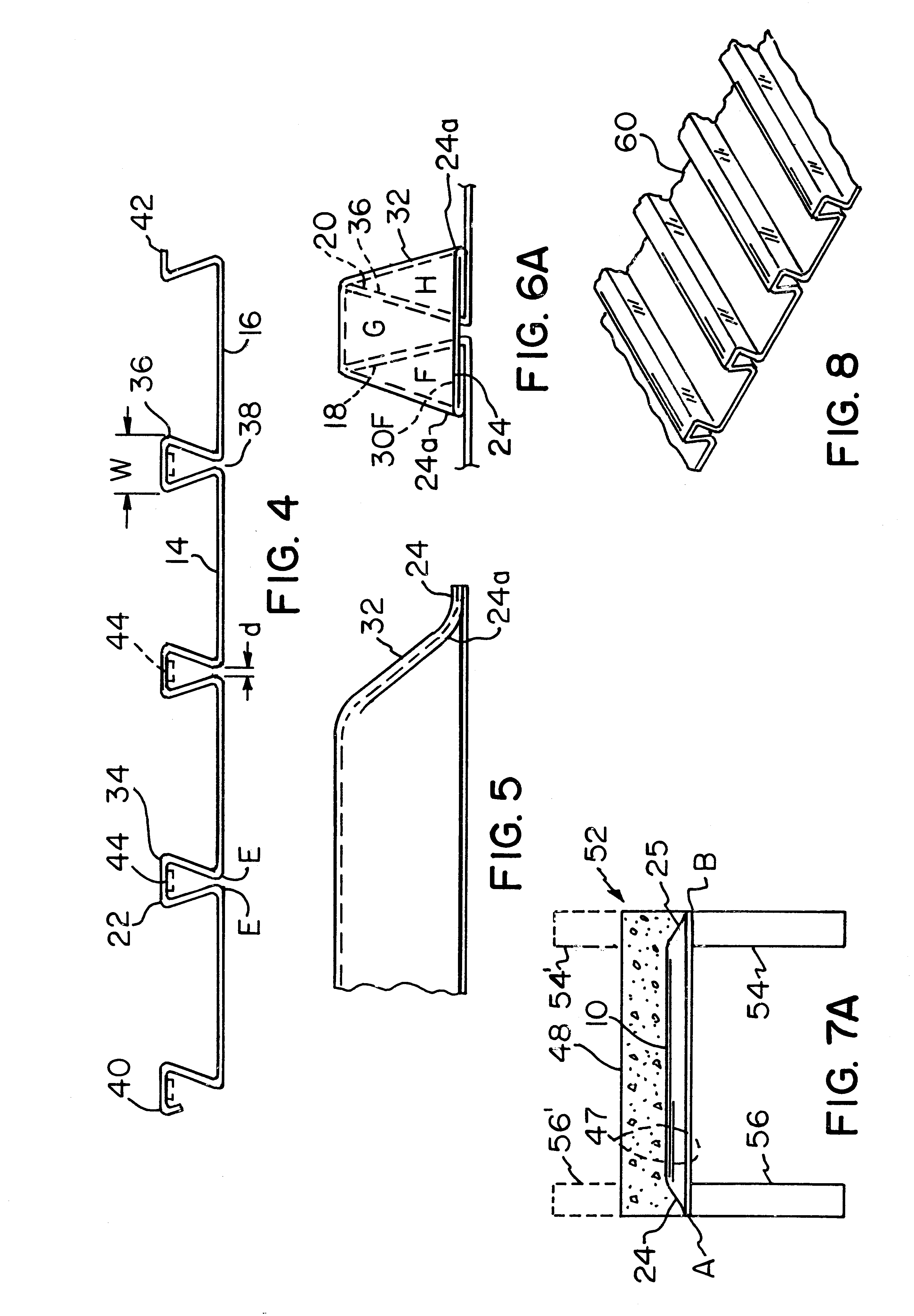
FIGS. 1-6B show a ribbed plate 10 for a composite deck made in accordance with the present invention. The ribbed plate 10 includes a substantially planar plate 12 having an upper surface 14, a lower surface 16 and longitudinally-spaced ends A and B. A plurality of laterally-spaced, longitudinally-extending protruding ribs 17 is provided. As can be seen, the ribs 17 define a keystone profile. Each of the ribs 17 includes laterally-spaced apart sidewalls 18 and 20 attached to a top wall 22 at one end. As shown in FIG. 2, the sidewalls 18 and 20 are angled at an angle a toward each other. Referring back to FIG. 1, the ribs 17 extend from a first end 24 to a second end 25 in a longitudinal direction defined along an axis X. A lateral direction is defined along axis Y and a vertical direction as defined by an axis Z as shown in FIG. 1. The first end 24 and the second end 25 of each rib 17 are closed. The closed first ends 24 and the second ends 25 of the ribs 17 are formed by crushing or...
PUM
| Property | Measurement | Unit |
|---|---|---|
| Structure | aaaaa | aaaaa |
| Width | aaaaa | aaaaa |
Abstract
Description
Claims
Application Information