
Microtool mount

a technology for microtools and mounts, applied in the field of microtool mounts, can solve the problems of high inconvenience, delay, and high cost of clamping, and achieve the effects of facilitating egress of lead, and reducing the risk of slipping

Inactive Publication Date: 2002-03-19
YAKOVENKO SERGEY A
View PDF11 Cites 8 Cited by
  • Summary
  • Abstract
  • Description
  • Claims
  • Application Information

AI Technical Summary

Benefits of technology

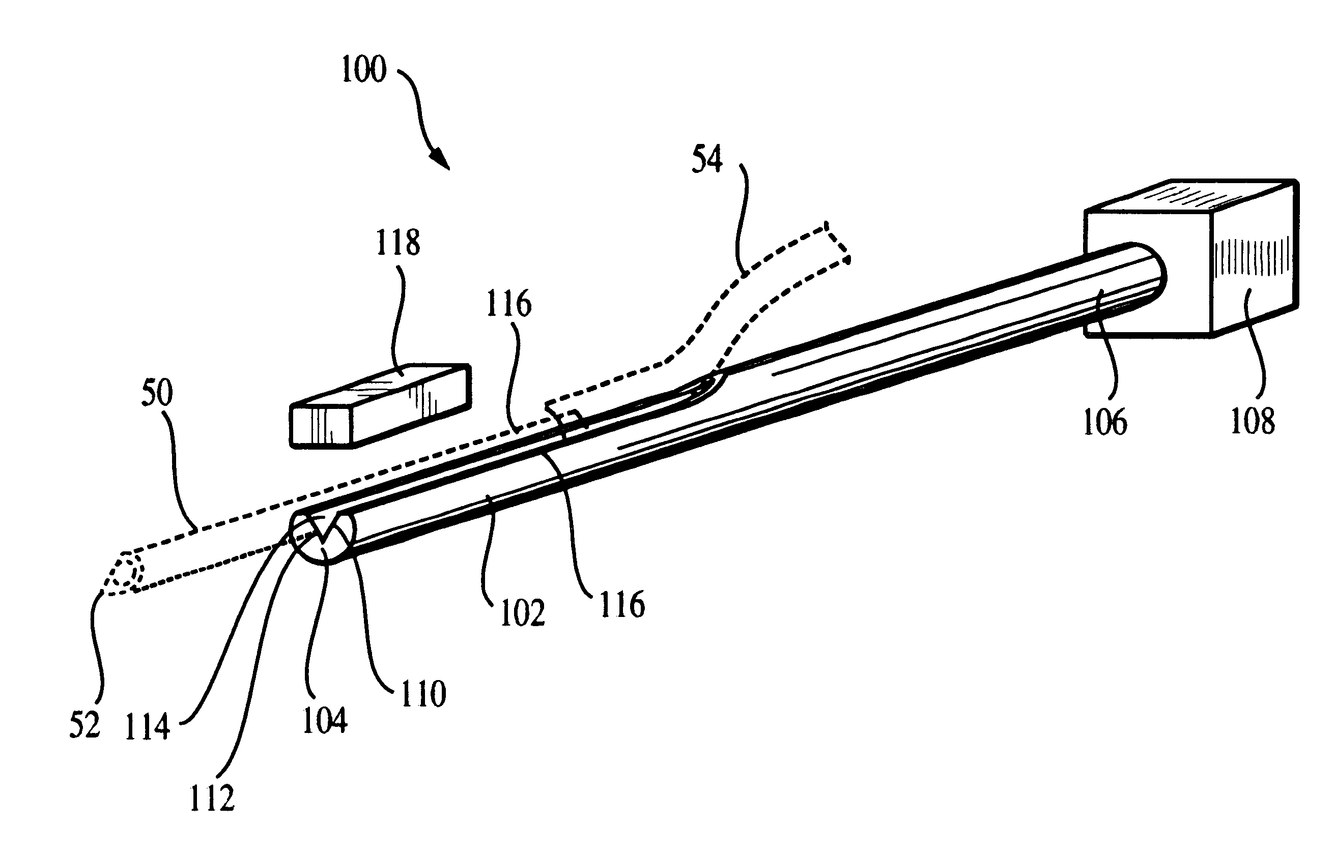
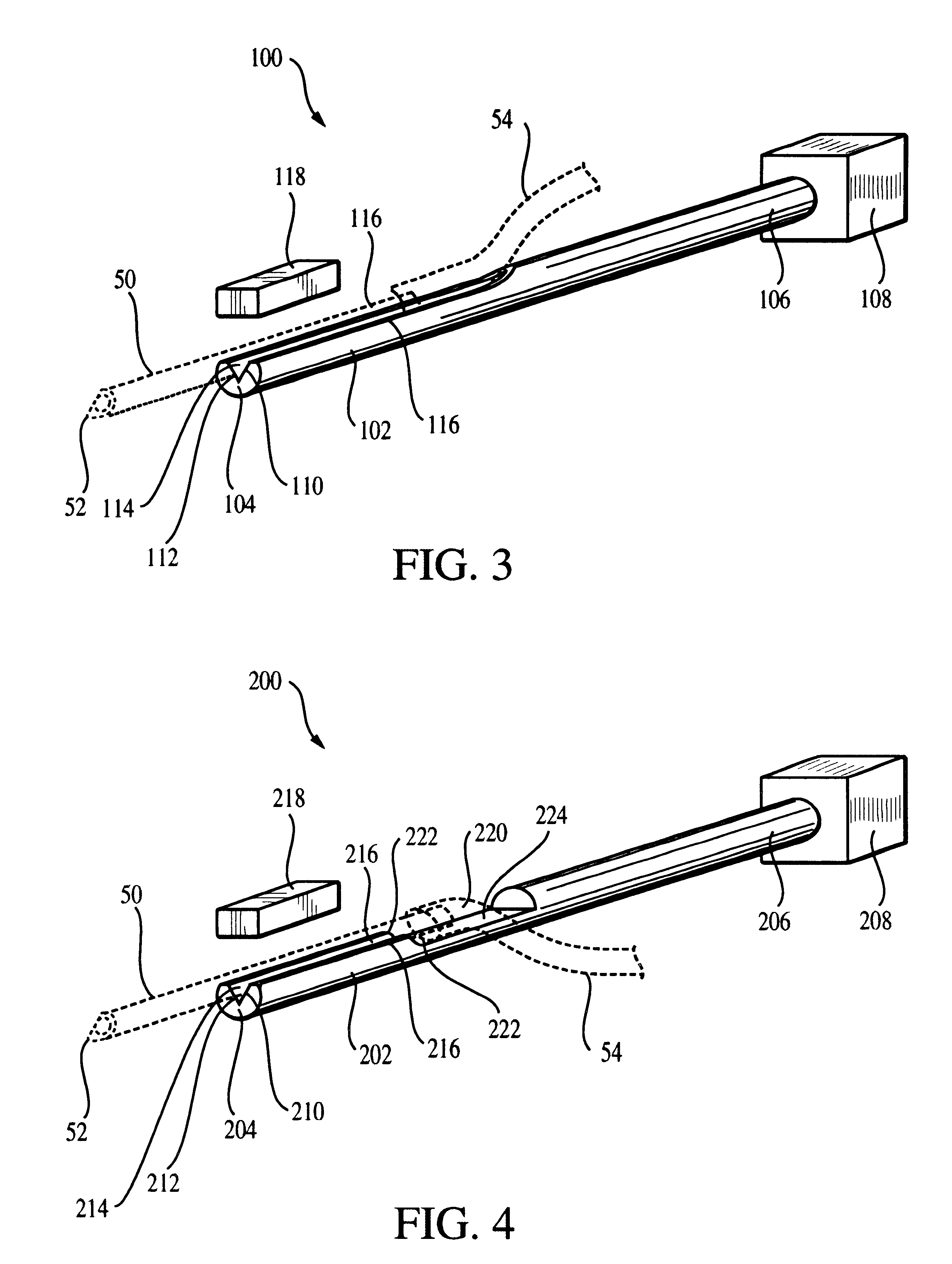
To summarize, the microtool mount (as best seen in the different embodiments of FIGS. 3-5) includes an elongated finger terminating in a tip. The finger has a pair of valley edges from which valley walls descend to terminate in a valley floor, thereby defining a valley between the valley walls and floor. The valley extends from the tip along a path parallel to at least a portion of the length of the finger. A microcapillary may be accommodated within the valley (see particularly FIGS. 3 and 4), and a fastening member, preferably a magnet, may be removably affixed to the finger above the valley to maintain the microcapillary within the valley. The valley edges are preferably planar along at least a portion of the length of the finger so as to provide an even surface whereupon the magnet may be more firmly affixed to the finger. The valley is preferably situated within the finger so that a microcapillary resting therein will be aligned with the longitudinal axis of the finger, so that rotation of the finger about this longitudinal axis will also cause the microcapillary to rotate about its longitudinal axis. This allows for greater ease in positioning the microcapillary at desired locations during a biological operation.
In certain preferred embodiments (such as those of FIGS. 4 and 5), at a location spaced rearward of the tip of the finger, one or more of the valley edges has a ledge from which the valley edge begins descending towards the valley floor. A gap is thereby defined in this valley edge and its valley wall. Such a gap may be defined in both valley edges / walls, as illustrated in FIG. 4, or the gap may be defined in one valley edge / wall, as illustrated in FIG. 5. This gap (or gaps) may therefore define a depressed pit spaced rearward from the tip of the finger, behind the mounting surface for the fastening member. The pit provides an enlarged area which better accommodates any flexible lead (e.g., an elastomeric tube, or a flexible wire) trailing from the end of a microtool maintained within the valley, and which allows easier egress of the lead from the finger (see particularly FIG. 4). As illustrated best by the embodiment of FIG. 6 (also shown in FIG. 5), the pit (the element labeled 324 in FIG. 6) may be depressed within the valley so that the length of a microcapillary resting forward of the lead will be cradled within the valley, and the portion of the lead which is fit over the end of the microcapillary will not bias the end of the microcapillary partially out of the valley.
As exemplified by the embodiment of FIG. 5, the valley edges may be formed in two sections, with a distal lower region adjacent to the tip and a proximal raised region spaced from the tip and separated from the lower region by a ledge. A fastening member accommodated on the lower region can therefore be accommodated against the ledge for greater resistance against slipping.

Problems solved by technology

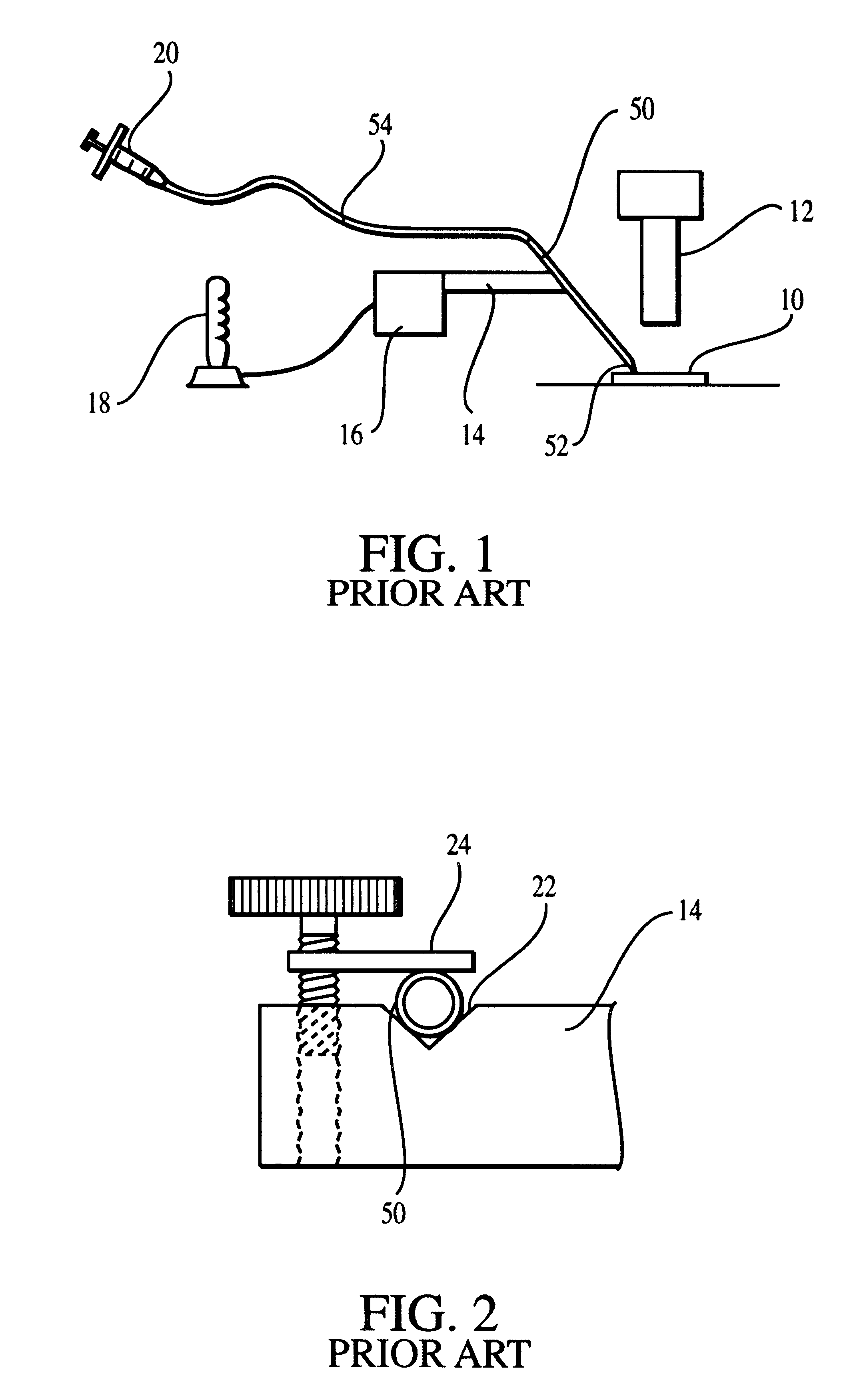
While this arrangement is simple to manufacture, operate, and maintain, it causes several significant difficulties with use of the microcapillary 50.
Breakage is highly inconvenient because the microcapillaries 50 take a long time to prepare, and are usually prepared right before an operation is to be performed to ensure that the microcapillaries 50 are uncontaminated with foreign matter.
This delay may be costly since the cellular material to be operated on may have a limited time window of viability.
Second, the clamp 24 is somewhat time-consuming to deal with.
Third, the mount 14 is difficult to use because the user must hold the microcapillary 50 in one hand and simultaneously tighten the clamp 24.

Method used


Image

  • Microtool mount
  • Microtool mount
  • Microtool mount

Examples


Embodiment Construction

Turning initially to FIG. 3, a first preferred version of the microtool mount is designated generally by the reference numeral 100. Since the structure and function of the microtool mount 100 is best understood when described with reference to a particular microtool, the microtool mount 100 will hereinafter be discussed in relation to its use with microcapillaries, and will thus be referred to as the capillary mount 100. However, it is emphasized that the mount 100 is not limited to use with microcapillaries and may be used with other microtools as well.

The capillary mount 100 includes an elongated finger 102 extending between a distal tip 104 and an opposing rod-like proximal end 106. The proximal end 106 can be rotatably journalled within a bearing 108 (which may take a variety of forms, with a simple block-like bearing 108 being illustrated here), or fastened within a micromanipulator, microforge, or the like. The finger 102 has a valley 110 defined along its length, with the val...


PUM


Abstract

A microtool mount includes an elongated finger terminating in a tip. The finger has a pair of valley edges from which valley walls descend to terminate in a valley floor, thereby defining a valley between the valley walls and floor. The valley extends from the tip along a path parallel to at least a portion of the length of the finger. A microcapillary or other rodlike microtool may be accommodated within the valley, and a fastening member, preferably a magnet, may be removably affixed to the finger above the valley to maintain the microtool within the valley. The valley edges are preferably planar along at least a portion of the length of the finger so as to allow the magnet to more firmly affix to the finger.

Description

This document corcerns as invention relating generally to mounting / gripping apparata for use in the handling and manipulation of microtools (i.e., precision instruments and manipulators for microtechnology and nanotechnology applications, such as fluid-transporting microcapillaries), and more specifically to mounting apparata for quickly and safely receiving and releasing fragile microcapillaries.Capillaries are commonly used in biological applications to sample and transport fluids and / or cells for testing or other purposes. When particularly fine biological microoperations are required--for example, injecting or removing cellular genetic material during in vitro fertilization or cloning operations--microcapillaries are generally used. Microcapillaries are ordinarily prepared by taking a standard glass capillary tube (usually having 1 millimeter diameter), and heating it until it becomes ductile. The capillary is then stretched, causing its diameter to contract. When the capillary ...

Claims


Application Information

Patent Timeline
IPC IPC(8): B01L9/00B25B11/00A61B19/00A61B17/00
CPCB25B11/002B01L9/50A61B2017/00345A61B2017/0046B01L2300/0838A61B2019/2249A61B34/72
Inventor YAKOVENKO, SERGEY A.
Owner YAKOVENKO SERGEY A
Learn More