Linear position sensor using a strain gage

a strain gage and position sensor technology, applied in the field of position sensors, can solve the problems of road contaminants, and inability to meet the requirements of all position sensing applications

Inactive Publication Date: 2002-04-09
CTS CORP ELKHART
View PDF16 Cites 23 Cited by
  • Summary
  • Abstract
  • Description
  • Claims
  • Application Information

AI Technical Summary

Problems solved by technology

These detection methods tend to each offer much value for one or more applications, but none meet all application requirements for all position sensing applications.
The limitations may be due to cost, sensitivity to particular energies and fields, resistance to contamination and environment, stability, ruggedness, linearity, precision, or other similar factors.
Transportation applications generally, and specifically automotive applications, are very demanding.
Temperatures may rise to 150 degrees Centigrade or more, with road contaminants such as salt and dirt splashing upon the engine compartment.
This may occur while the engine is still extremely hot from operation.
However, the resistive position sensors are not without limitations.
However, magnetic position sensors have issues with linearity and maintaining tolerances.
Regardless of the arrangement and method for changing the field about the sensor, the magnetic circuit faces several obstacles which degrade the performance of magnetic position sensors.
Since this will not be detected by the sensor, the sensor will provide a reading of insufficient magnitude.
Failure to do so will result in unpredictable magnet performance.
However, operating at complete saturation leads to another problem referred to in the trade as irreversible loss.
Temperature cycling, particularly to elevated temperatures, permanently decreases the magnetic output.
Another significant challenge in the design of magnetic circuits is the sensitivity of the circuit to surrounding ferromagnetic objects.

Method used


Image

  • Linear position sensor using a strain gage
  • Linear position sensor using a strain gage
  • Linear position sensor using a strain gage

Examples


Embodiment Construction

(s)

Linear Position Sensor

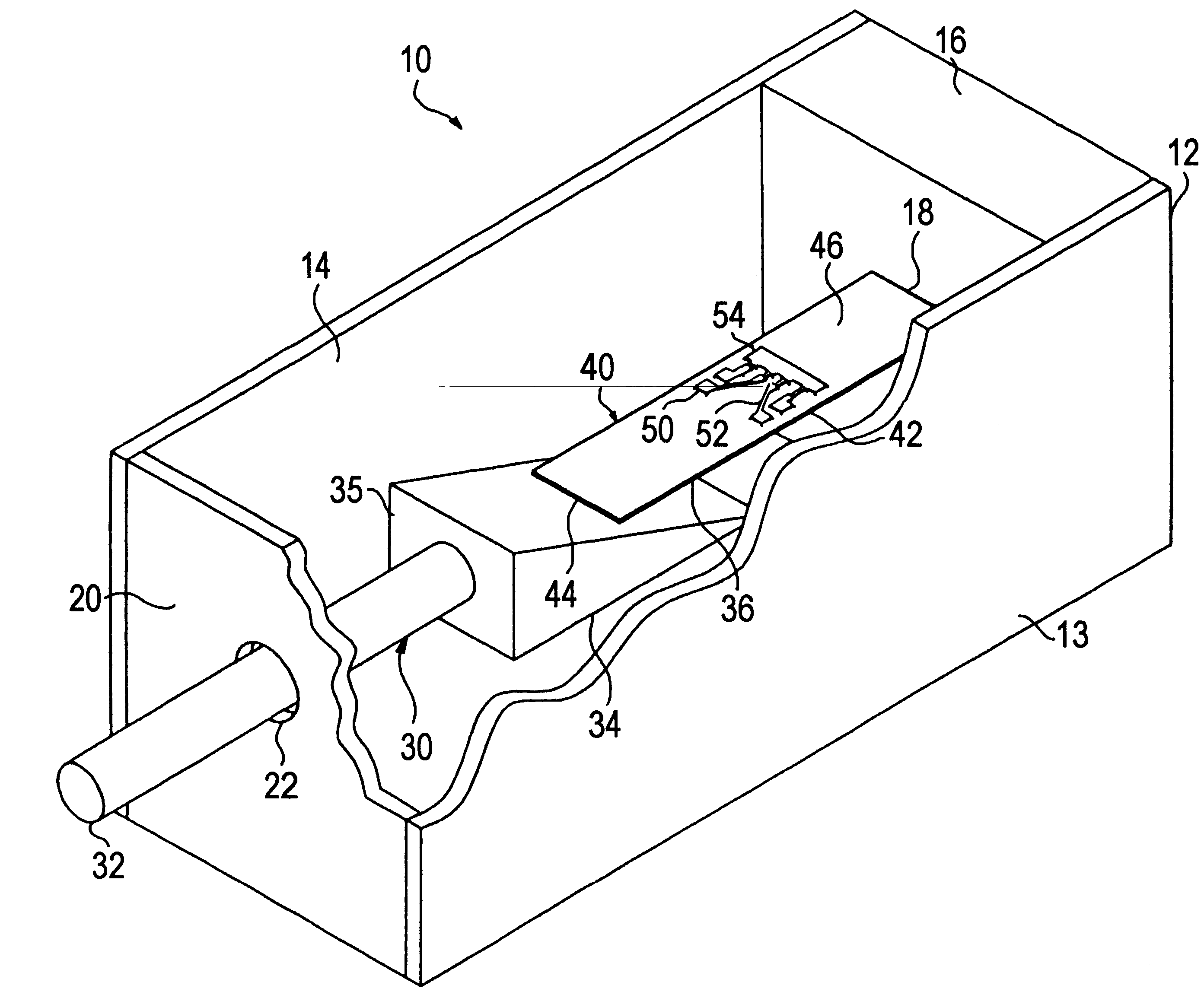
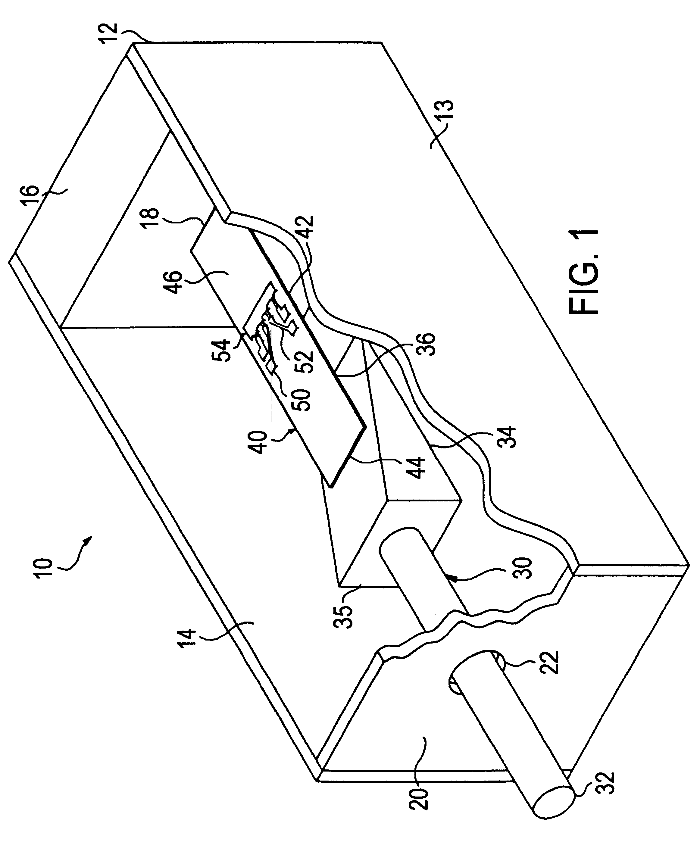
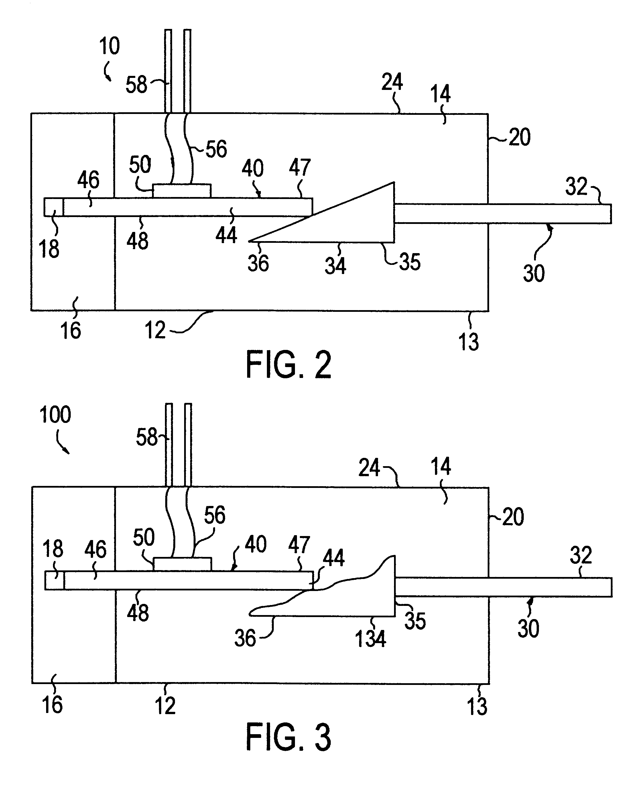
Referring to FIGS. 1 and 2, a preferred embodiment of a linear position sensor using a strain gage 10 is shown. A housing 12 has outer walls 13 that define a cavity 14. Housing 12 has an end 16 with a slot 18 and an end 20 with a hole 22. A cover 24 is mounted over housing 12 to seal cavity 14. Housing 12 and cover 24 can be formed from injection molded plastic. Cover 24 is ultrasonically welded or heat staked to housing 12 to seal the sensor 10.

An actuator 30 is mounted in cavity 14. Actuator 30 has a shaft 32 attached to a sloping or tapered ramp 34. Ramp 34 has a thick end 35 and a thin end 36. Shaft 32 is attachable to an object whose position is desired to be measured such as an EGR valve. A sensor or strain gage 40 is located inside cavity 14. Sensor 40 has a substrate 42 with ends 44 and 46, an upper surface 47 and a lower surface 48. End 46 is press fit into slot 18 in order to hold the sensor. Substrate 42 is preferably formed from 430 stainless ste...


PUM

PropertyMeasurementUnit
thickaaaaaaaaaa
durableaaaaaaaaaa
electricalaaaaaaaaaa

Abstract

A linear position sensor for sensing the position of an attached object. The linear position sensor uses a strain gage to detect the position of the object. The sensor includes a housing and a ramp shaped actuator located in the housing. The actuator is attachable to the object. A strain gage is positioned in contact with the actuator. The actuator applies a strain to the strain gage as the actuator is moved. The strain gage generates an electrical signal that is proportional to the position of the object.

Description

1. Field of the InventionThis invention pertains to position sensors which are both durable and precise for application in rugged and demanding environments, particularly for application with internal combustion engines.2. Description of the Prior ArtThere are a variety of known techniques for position sensing. Optical, resistive, electrical, electrostatic and magnetic fields are all used with apparatus to measure position. There are many known apparatus for using these energies for sensing. A few of the known apparatus are resistive contacting sensors, inductively coupled ratio detectors, variable reluctance devices, capacitively coupled ratio detectors, optical detectors using the Faraday effect, photo-activated ratio detectors, radio wave directional comparators, and electrostatic ratio detectors. There are many other known detectors, too numerous to mention herein.These detection methods tend to each offer much value for one or more applications, but none meet all application re...

Claims


Application Information

Patent Timeline
Patent Type & Authority Patents(United States)
IPC IPC(8): G01D5/02G01D5/04
CPCG01D5/04G01D2205/77G01D2205/775G01D5/183
Inventor OSMER, WILLIAM G.RAINEY, ROBERT
Owner CTS CORP ELKHART
Why Eureka
Try Eureka