Thrust plate assembly

a technology of thrust plate and assembly plate, which is applied in the direction of friction clutches, clutches, mechanical actuated clutches, etc., can solve the problems of insufficient wear compensation, inability to interact with the various components in the intended manner, and wear overcompensation

Inactive Publication Date: 2002-04-16
MANNESMANN SACHS AG
View PDF17 Cites 12 Cited by
  • Summary
  • Abstract
  • Description
  • Claims
  • Application Information

AI Technical Summary

Benefits of technology

In a construction of this kind, it becomes possible for the blocking / detection element to be designed, in terms of the prestressing force provided for it, so that in every operating state, that is to say every state of wear, this force is always sufficient to prevent unintended wear compensation in the event of action taken on the wear-adjusting device. That is to say, the blocking / detection element may, in principle, be prestressed against the wear-compensating device with a force which is markedly higher than that force by which the at least one wear-adjusting element is prestressed for the purpose of movement in the wear-adjusting direction. This becomes possible since the provision of the detaining element avoids the need to ensure a force equilibrium between these two forces.
Furthermore, in the thrust plate according to the invention, there is preferably provision for the at least one play indicator arrangement to be capable of being brought by means of the resetting arrangement into a position which corresponds to a state of lower wear. This may be implemented in a simple way, for example, in that, by means of the resetting arrangement, the detention of the blocking / detection element against movement in its prestressing direction is capable of being canceled.

Problems solved by technology

If the leaf spring element is somewhat too soft, there is the risk that wear overcompensation will take place, and, if the leaf spring element is too rigid, there is the risk that the wear will not be sufficiently compensated for and that the interaction of the various components cannot take place in the intended way.
With the clutch engaged, however, the wear-adjusting device, and therefore also the at least one adjusting element, is initially still acted upon by the diaphragm spring and therefore cannot carry out a compensating movement.
In friction clutches in which, as described above, the compensation of wear occurring in the region of the friction linings of the clutch disk can be carried out automatically by means of the displacement of any components of a wear-adjusting device, there is basically the problem that, when, for example after the friction linings have been worn away completely, the clutch disk is replaced by a new clutch disk with unworn friction linings, various components in the region of the wear-adjusting device are not in a position which corresponds to such a new unworn state of the friction linings.
This may present the problem that the force accumulator, that is to say, for example, a diaphragm spring, may not work in the desired position range during subsequent operation and there is therefore a correspondingly undesirable spring characteristic.

Method used


Image

  • Thrust plate assembly
  • Thrust plate assembly
  • Thrust plate assembly

Examples


Embodiment Construction

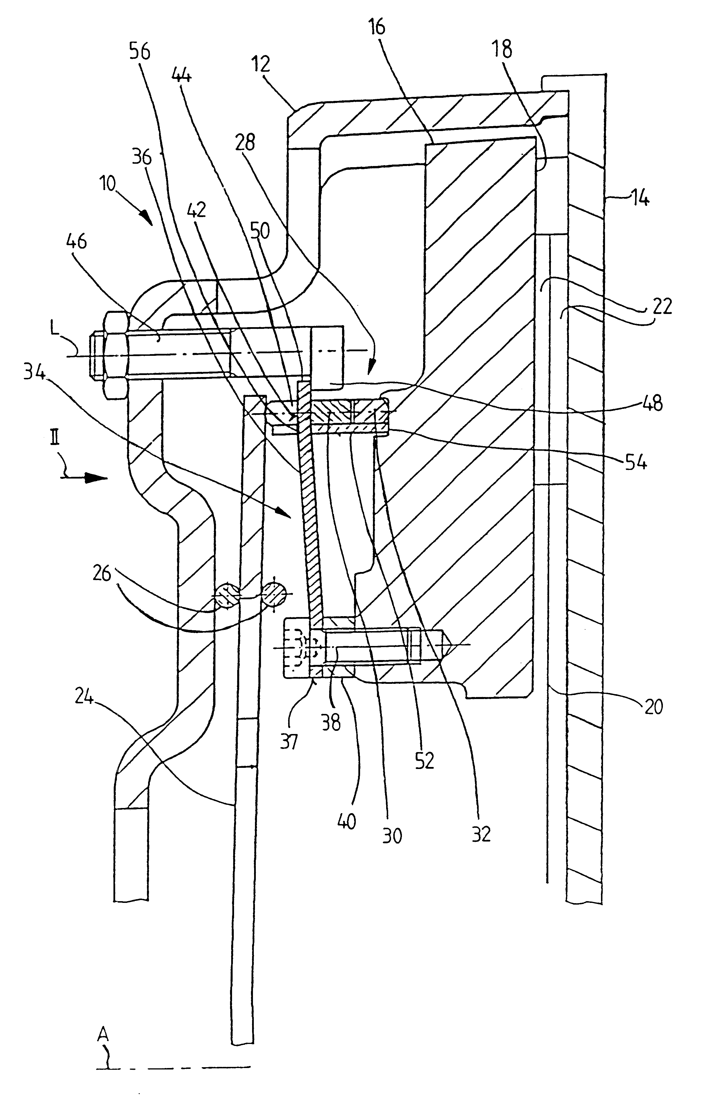
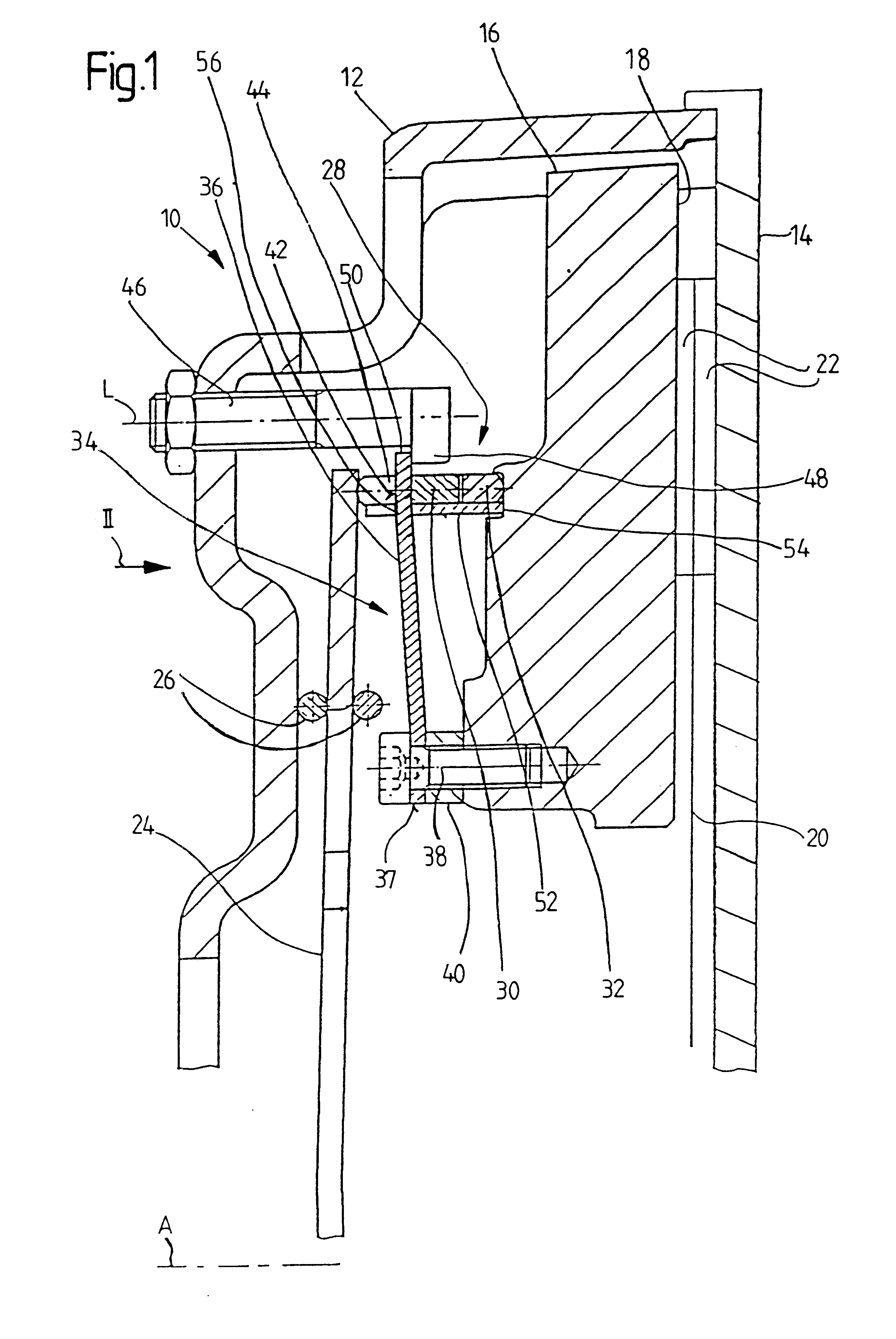
FIG. 1 shows part of a thrust plate subassembly 10 according to the invention in longitudinal section. The thrust plate subassembly 10 comprises a housing 12 which, in a way known per se, can be assembled together with, that is to say connected fixedly in terms of rotation to, a flywheel 14 illustrated diagrammatically in FIG. 1, in order to form a motor vehicle friction clutch. The housing 12 is then rotable together with the flywheel 14 about an axis of rotation A.

Arranged in the housing 12 is a pressure plate 16 which is connected to the housing 12 so as to be displaceable in the direction of the axis of rotation A, but fixedly in terms of rotation, by means of tangential leaf springs or the like. A clutch disk 20, illustrated diagrammatically, together with its friction linings 22, is clampable, in the clutch engaged state, between a friction surface 18 of the pressure plate 16 and the flywheel 14. A diaphragm spring 24, which forms the force accumulator in the embodiment illust...


PUM


Abstract

A thrust plate subassembly comprises a play indicator arrangement that includes: a blocking / detection element which is mounted on the one component and which is prestressed with a blocking portion against the wear-adjusting device and acts upon the wear-adjusting device to prevent a movement of the at least one wear-adjusting element in the wear-adjusting direction. A detection portion of the detection element is in or is capable of being brought into interaction with another component or subassembly displaceable relative to the one component on the occurrence of wear, for the purpose of detecting the wear. On the occurrence of wear the blocking / detection element being capable of being brought, as a result of the interaction with the other component, into a position for releasing the at least one adjusting element for the purpose of movement in the adjusting direction. Furthermore, a detaining element is provided, by which, when the blocking / detection element is brought into its position for releasing the at least one adjusting element, the blocking / detection element is capable of being detained against movement in its prestressing direction.

Description

1. Field of the InventionThe present invention relates to a thrust plate subassembly, in particular for a motor vehicle friction clutch with automatic wear compensation comprising a housing which is fixable or fixed to a flywheel for joint rotation about an axis of rotation, a pressure plate arranged essentially fixedly in terms of rotation in the housing and axially displaceable relative to the latter, a force accumulator, preferably diaphragm spring, which is supported on the housing, on the one hand, and on the pressure plate, on the other hand, and presses the pressure plate in the direction of a side of the housing which is provided for connection to the flywheel, a wear-adjusting device arranged in the support path of the force accumulator between the force accumulator and one component of housing and pressure plate and having at least one adjusting element displaceable for wear compensation and prestressed in a wear-adjusting direction, and at least one play indicator arrange...

Claims


Application Information

Patent Timeline
Patent Type & Authority Patents(United States)
IPC IPC(8): F16D13/58F16D13/75
CPCF16D13/757F16D2013/581
Inventor WEIDINGER, REINHOLD
Owner MANNESMANN SACHS AG
Why Eureka
Try Eureka