High-pressure orifice plate gas stagnation temperature control device and method

A control device and stagnation temperature technology, applied in the direction of temperature control, measurement device, test/calibration device, etc. by electric means, can solve problems such as short heat exchange time, pipeline blasting accidents, and affecting pipeline pressure resistance , to achieve the effect of ensuring the accuracy of measurement and improving accuracy

Active Publication Date: 2017-02-22
BEIJING AEROSPACE INST FOR METROLOGY & MEASUREMENT TECH +1
View PDF4 Cites 2 Cited by
  • Summary
  • Abstract
  • Description
  • Claims
  • Application Information

AI Technical Summary

Problems solved by technology

Because this system belongs to the category of high-pressure and high-speed pipe flow, the gas flow rate is fast, and the heat exchange time must be very short. The method of constant temperature water bath or constant temperature oil bath will not achieve good results, and directly heating the high-pressure

Method used


Image

  • High-pressure orifice plate gas stagnation temperature control device and method
  • High-pressure orifice plate gas stagnation temperature control device and method
  • High-pressure orifice plate gas stagnation temperature control device and method

Examples


Example Embodiment

[0036] The present invention will be described in detail below with reference to the drawings and specific embodiments.

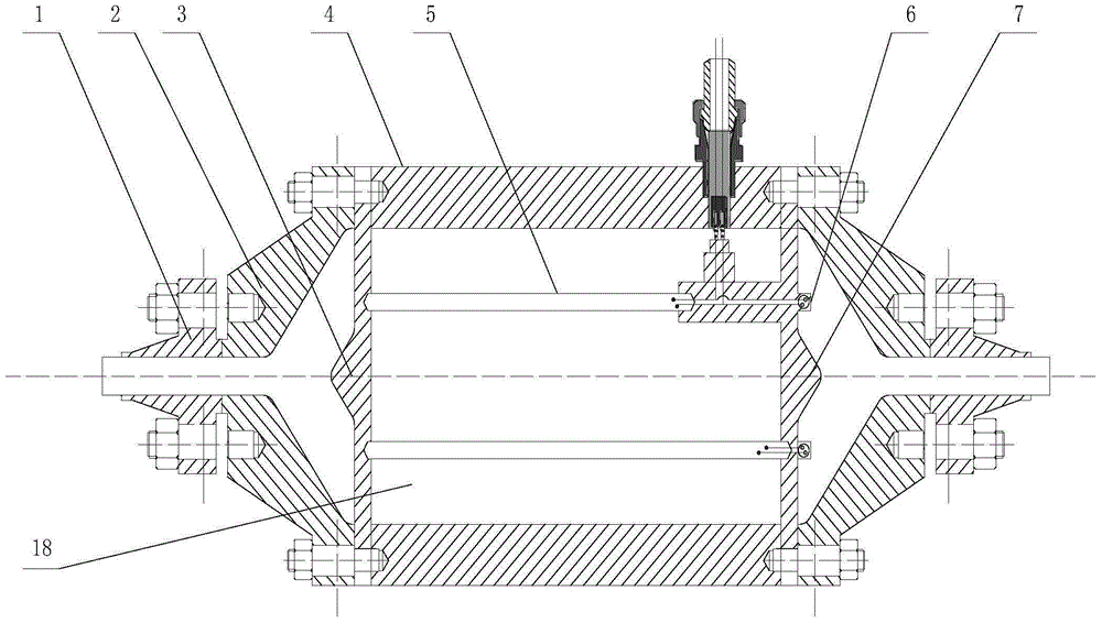
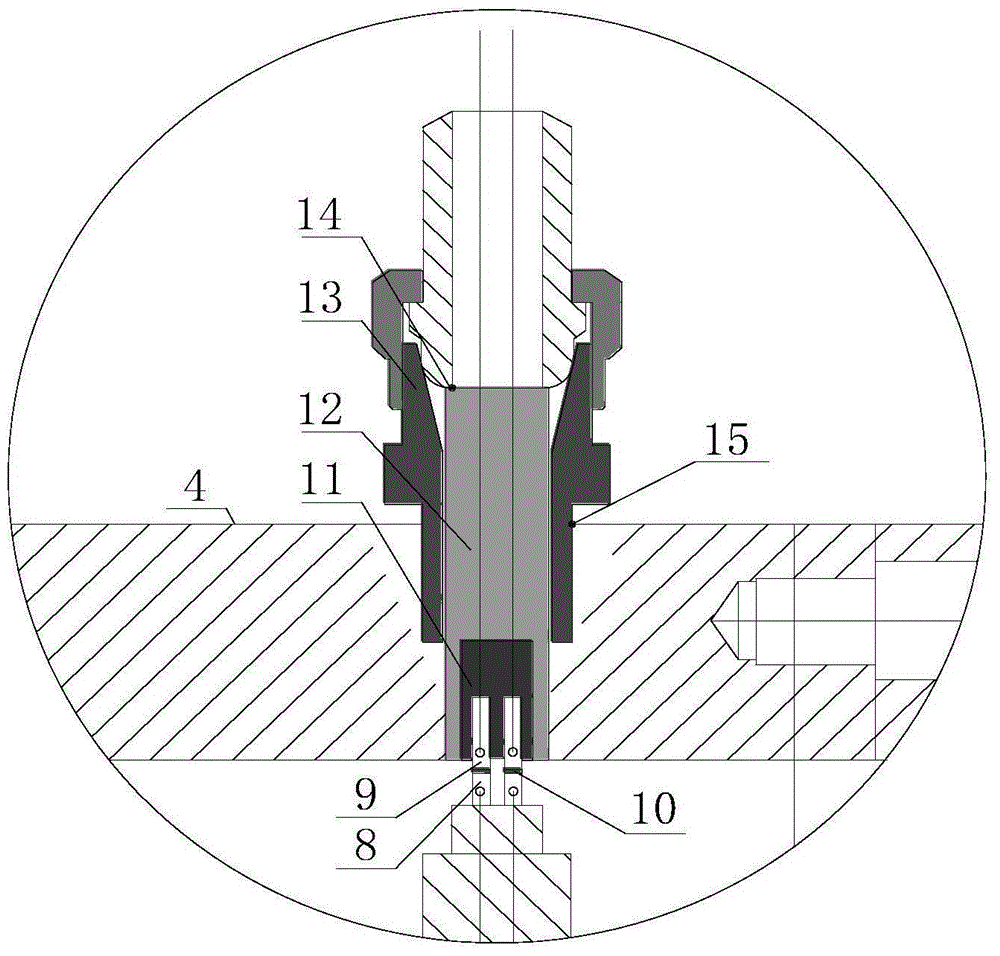
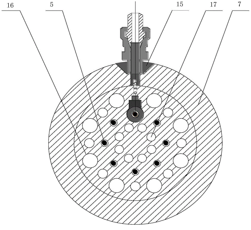
[0037] Such as figure 1 — image 3 As shown, the high-pressure orifice gas stagnation temperature control device of the present invention, that is, the temperature-controlled gas tank 18 includes a temperature-controlled gas tank inlet flange 1, a temperature-controlled gas tank inlet expansion splint flange 2, a front porous rectifier plate 3. Temperature control gas tank wall 4, electric heating rod 5, collecting coil 6, rear porous rectifier plate 7, electric heating rod inner electrode 8, outer electrode 9, electrode spring 10, insulating material 11, metal plug 12, ball head-cone sealing structure 13. Welding point A 14, welding point B15, outer ring diversion hole 16, inner ring diversion hole 17;

[0038] The inlet flange 1 of the temperature-controlled gas tank is connected to the outlet of the gas source, and the front porous rectifier plate 3 is clamp...


PUM


Abstract

The present invention belongs to the orifice plate gas flow measurement technical field and relates to a high-pressure orifice plate gas stagnation temperature control device and method. The control device is a temperature control gas tank; a temperature control gas tank inlet flange is externally connected with the outlet of a gas source; a front porous rectifying plate is clamped to a temperature control gas tank wall through a temperature control gas tank inlet expanding type clamp plate flange by means of bolts; electric heating rods are fixedly clamped to a rear porous rectifying plate through the front porous rectifying plate; line collection rings are located on the rear porous rectifying plate; electrode springs are clamped between electric heating rod inner electrodes and external electrodes; the external electrodes are embedded in insulating materials; the insulating materials are embedded in metal plugs; the metal plugs are welded to ball head-taper surface sealing structures; the ball head-taper surface sealing structures are welded to the temperature control gas tank wall; and outer periphery flow guiding holes and inner periphery flow guiding holes are located on the rear porous rectifying plate. With the high-pressure orifice plate gas stagnation temperature control device and method of the invention adopted, gas temperature at the inlet of an orifice plate can be effectively compensated in a certain range, the accuracy of key parameter measurement participating in the calculation of the discharge coefficient of the orifice plate can be ensured, and the accuracy of the calibration of the discharge coefficient of the orifice plate can be improved.

Description

technical field [0001] The invention belongs to the technical field of orifice gas flow metering, and in particular relates to a high-pressure orifice gas stagnation temperature control device and method. Background technique [0002] The high-pressure orifice gas large flow calibration device uses the system group composed of parallel standard sonic nozzles as the standard meter, and the positive pressure PVTt device as the main standard. The gas flow rate of the orifice plate to be calibrated is obtained by calibrating the sonic nozzle group. : The gas modulated by the gas source and gas distribution system flows through the orifice plate to be calibrated and the standard sonic nozzle group sequentially. By measuring the temperature and pressure in the stagnant container before the sonic nozzle group, the mass flow rate q of a single sonic nozzle i From formula (1) get: [0003] [0004] In the formula: A is the throat area of ​​the sonic nozzle; R and M are the univer...

Claims


Application Information

Patent Timeline
IPC IPC(8): G05D23/19G01F25/00
Inventor 孙凤举王慧龙马方超雒宝莹焦鑫鑫罗兆明钟山
Owner BEIJING AEROSPACE INST FOR METROLOGY & MEASUREMENT TECH
Why Eureka
Try Eureka