
Chainsaw bar guard

a chainsaw and bar guard technology, applied in the direction of metal sawing devices, sawing devices, sawing apparatuses, etc., can solve the problems of unattractive individuals using, damage to sharp edges, and injuries to individuals

Inactive Publication Date: 2002-05-21
PAQUIN JOSEPH GERALD RONALD
View PDF17 Cites 29 Cited by
  • Summary
  • Abstract
  • Description
  • Claims
  • Application Information

AI Technical Summary

Benefits of technology

The solution offers comprehensive protection for both the user and the chainsaw during transport, is easy to attach and detach, and does not interfere with carrying the chainsaw, while being cost-effective and adaptable to various chainsaw models.

Problems solved by technology

Because of the sharp edges of cutter chains and also of saw dogs when present on conventional chainsaws, chainsaws may cause injuries to the individuals carrying or handling the chainsaws, and their sharp edges may be damaged by unintended contact with objects.
However, the substantial weight and volume of such cases rendered them unattractive to individuals using them, especially loggers, who frequently have to carry chainsaws on foot to working sites.
However, in many such proposed devices, the protection of the individual primarily sought was protection during the sawing operation, not primarily protection during carrying or transporting the chainsaws.
Therefore, a portion of the cutter chain was always exposed when using such devices; the possibility of damage or injury during transportation was not prevented.
The Shivers bar guard is expensive and awkward to use; it remains attached to the saw during the sawing operation while it is pivoted upwards away from the guard, interfering with the operator's view of the log or other workpiece.
Other such protective devices often required some modification of the chainsaw itself.
As a result, the combined chainsaw and guard remained hazardous to the person carrying the chainsaw with the sheath thereon.
For example, since the tension springs were hooked onto the chainsaw handle bar, the springs often interfered with carrying the chainsaw.
Thus, it was quite possible that the person carrying the chainsaw with the sheath thereon might be injured by the tension spring if it were accidentally dislodged.
Therefore, simply by using the prior Otoupalik device, the risk of at least some types of injury increased.
The telescoping sheath described by Woleslagle is awkward to use and necessarily bulky at one end to accommodate the series of telescoping elements when they are collapsed.
Further, although not quite uniformly placed or spaced from one saw design to another, the nuts are placed and spaced quite similarly from one chainsaw to another.
A somewhat less expensive and generally satisfactory manufacture of the guard can be effected using sheet steel for the sleeve and welding the snap-fit mechanism thereto; this solution entails some slight risk of dulling saw teeth if and when they come into frictional or impact contact with the guard, but the risk is probably acceptable because the saw teeth become dull with use in any case.
That alternative would undesirably add to the weight, manufacturing cost, complexity (which would probably have a deleterious effect on the mechanical reliability of the sleeve) and bulk of the guard.
That alternative is considered undesirable because it could lead to premature loosening of one or both nuts and would interfere with the bar adjustment process.

Method used


Image

  • Chainsaw bar guard
  • Chainsaw bar guard
  • Chainsaw bar guard

Examples


Embodiment Construction

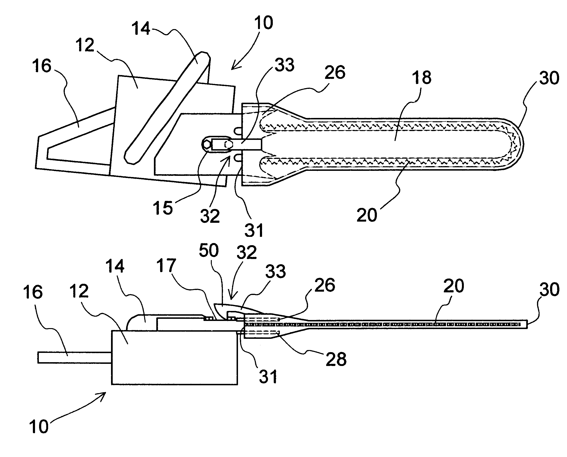
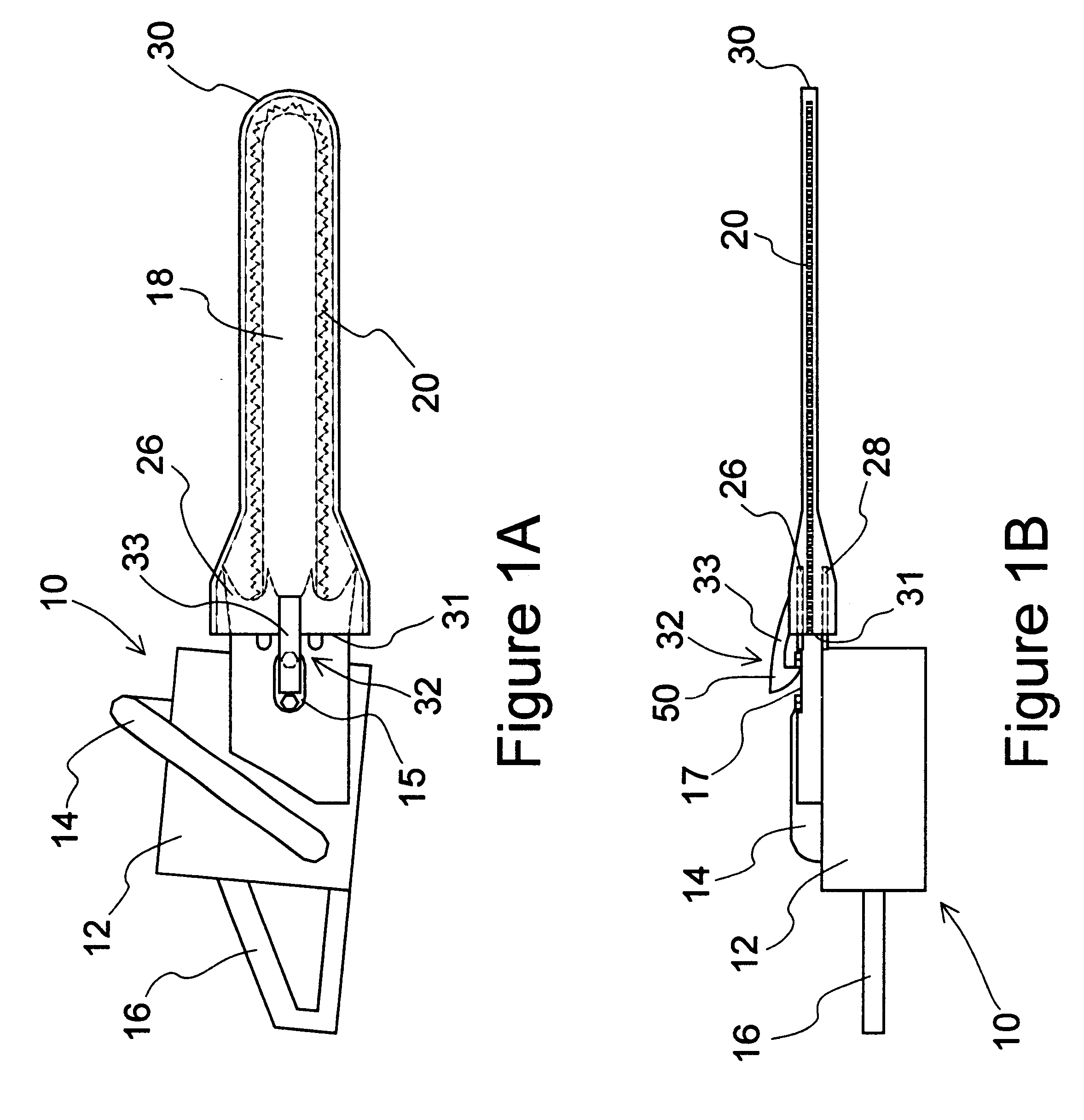
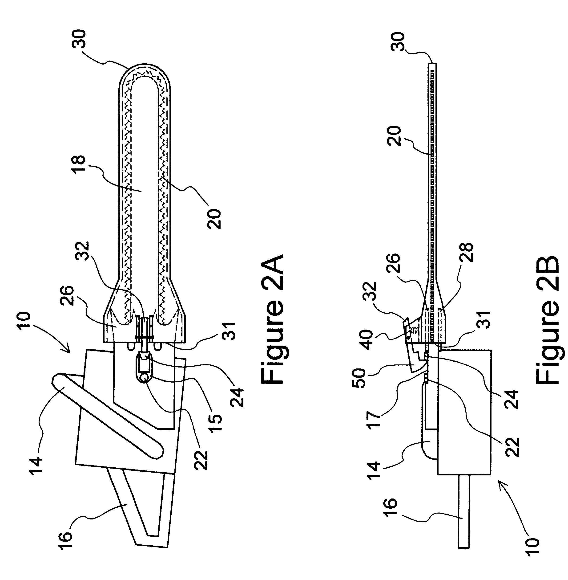
Referring to FIGS. 1A, 1B, 2A and 2B, a conventional power chainsaw 10 is disclosed having a motor housing 12, support handles 14 and 16, a forwardly projecting guide bar 18 around the slotted perimeter of which is slidably mounted an endless cutter chain 20, two guide bar adjustment nuts 22, 24, and two saw dogs 26, 28 on either side of the guide bar 18. The cutter chain is driven by a drive sprocket (not illustrated) within the housing 12. The adjustment nuts 22, 24 mate with corresponding attachment / adjustment bolts (not specifically illustrated) that pass through cut-out slots in the guide bar 18 and pass through a chainsaw bar mounting plate or mounting frame element 15 attached to the housing 12 or attached to a frame portion of the chainsaw 10 not specifically illustrated, or constituting a part of such housing or frame, whereby the guide bar 18 is secured to the chainsaw frame or to the housing 12 and may be adjustably positioned relative thereto by loosening the nuts 22, 24...


PUM

PropertyMeasurementUnit
lengthaaaaaaaaaa
weightaaaaaaaaaa
volumeaaaaaaaaaa

Abstract

An easily engageable and releasable chainsaw bar guard for protecting an individual carrying a chainsaw and for preventing damage to the cutter chain and saw dogs of a chainsaw. The bar guard comprises an elongated stiff hollow sleeve whose interior space is just slightly larger than the bar and chain to be protected. The sleeve has an opening at the proximal end for sliding the sleeve onto the guide bar, and is closed at the other end to protect the end of the bar and cutter chain. A snap-clip mechanism is fixed to the sleeve for releasably latching the proximal end of the guard to the chainsaw. The snap-clip mechanism biases a retaining claw into contact with the chainsaw bar between the nuts on the saw bar attachment / adjustment bolts. The sleeve and the snap-clip mechanism can be selectively configured to accommodate chainsaw bars of different shapes and dimensions and the spacing of whose guide bar adjustment nuts varies. The guard may optionally be provided with clips, pockets or containers for storing chainsaw tools.

Description

1. Field of the InventionThis invention relates to a protective guard for conventional portable chainsaws, including those with saw dogs. This invention is suitable for use when a chainsaw is carried, transported, or stored, thereby reducing the possibility of injury to the individual carrying or handling the chainsaw, and also reducing the possibility of damaging the cutter chain or saw dogs of the chainsaw during such activities.2. Description of the Prior ArtBecause of the sharp edges of cutter chains and also of saw dogs when present on conventional chainsaws, chainsaws may cause injuries to the individuals carrying or handling the chainsaws, and their sharp edges may be damaged by unintended contact with objects.One way previously proposed to minimize the risk of such injuries and damage was to place a chainsaw in a sealed portable case or similar container. However, the substantial weight and volume of such cases rendered them unattractive to individuals using them, especially...

Claims


Application Information

Patent Timeline
Patent Type & Authority Patents(United States)
IPC IPC(8): B27B17/02B27G19/00B27B17/00
CPCB27G19/003B27B17/02
Inventor PAQUIN, JOSEPH GERALD RONALD
Owner PAQUIN JOSEPH GERALD RONALD
Learn More