
Portable computer system with adjustable display subsystem

a subsystem and computer technology, applied in the field of portable computer systems, can solve the problems of low degree of freedom in designing the computer system 100, difficulty in operator's ability to catch the sounds emitted from the speakers, and low usability

Inactive Publication Date: 2002-05-21
AU OPTRONICS CORP
View PDF31 Cites 125 Cited by
  • Summary
  • Abstract
  • Description
  • Claims
  • Application Information

AI Technical Summary

Problems solved by technology

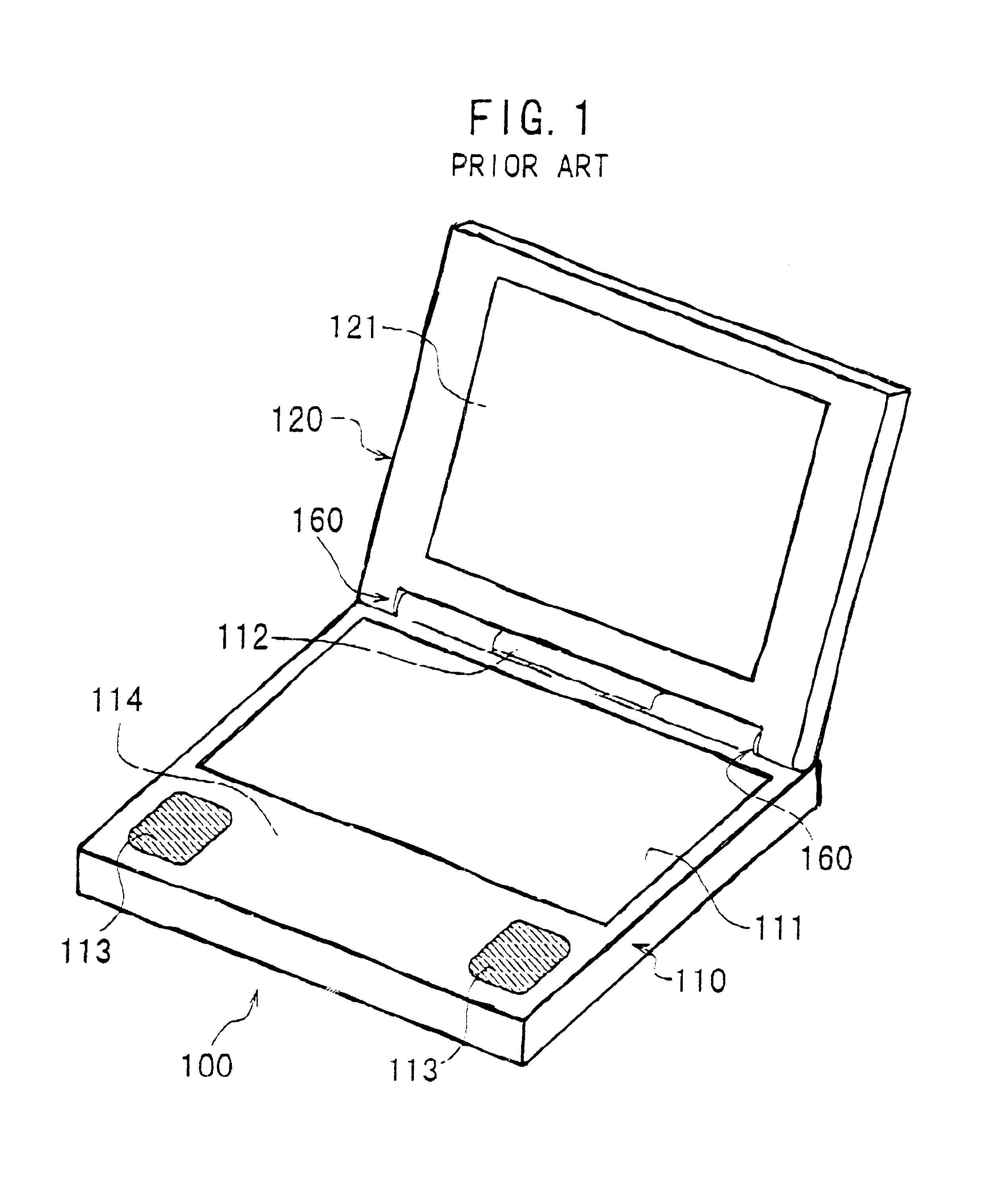
With the conventional portable computer system 100 described above, however, there is a problem that not only the degree of freedom in designing the computer system 100 is low but also usability for the operator is not satisfactory.
Therefore, the speakers 113 will be excessively near to the operator and accordingly, the operator tends to be difficult to catch the sounds emitted from the speakers 113.
Thus, the operator tends to be difficult to catch the sounds emitted from the speakers 113 due to this reason.
Therefore, the speaker needs to be very compact.
Moreover, due to the location, shape, and size of the indicator 112, the operator will be difficult to recognize the information visually displayed by the indicator 112.
In this case, the characteristic and convenience of the LCD unit are unable to be effectively utilized in the conventional computer system 100.
With the conventional supporting structure disclosed in the Japanese Non-Examined Utility-Model Publication No. 5-36523, however, the above-described problem is unable to be solved.
As a result, there arises a problem that the screen of the display unit becomes narrower due to existance of the intermediate supporting member as long as the size of the computer body is not enlarged.

Method used


Image

  • Portable computer system with adjustable display subsystem
  • Portable computer system with adjustable display subsystem
  • Portable computer system with adjustable display subsystem

Examples


first embodiment

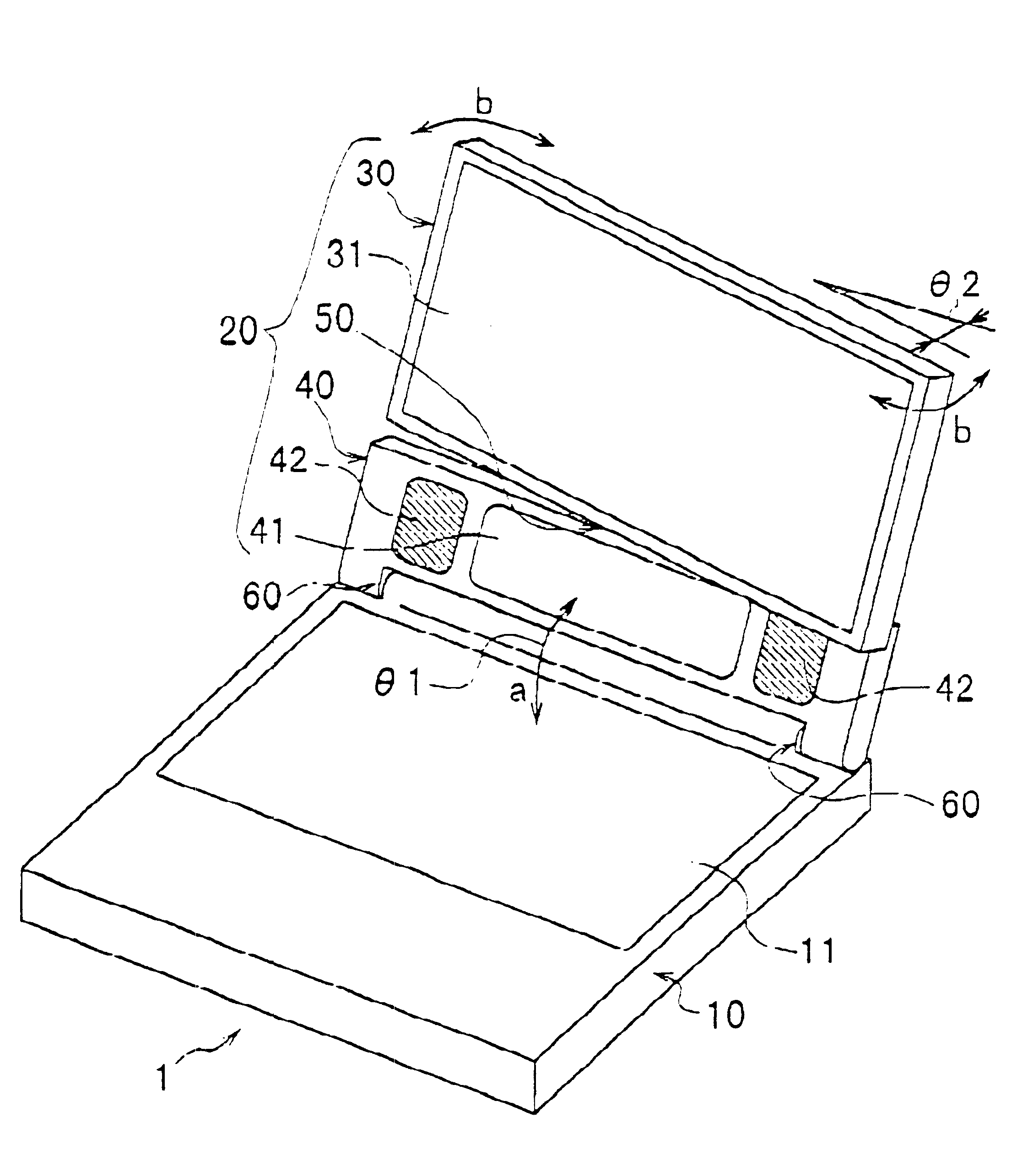
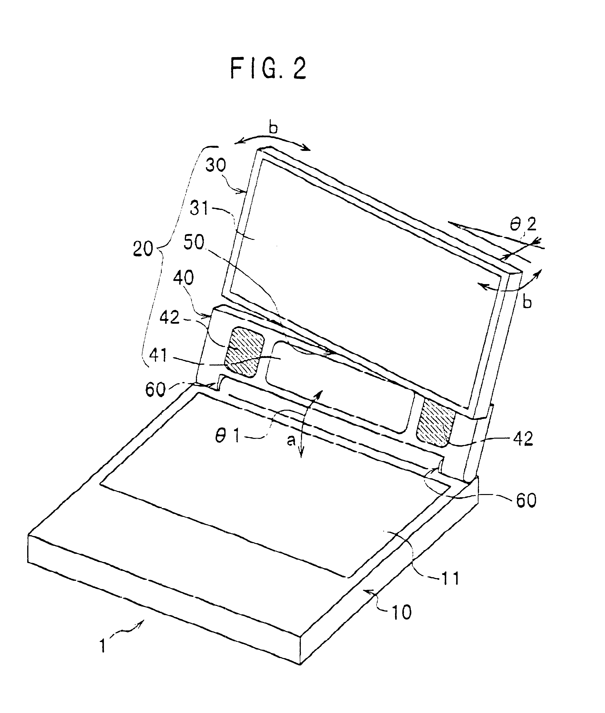
FIGS. 2 to 5 show a portable computer system according to the present invention, which is called a laptop or notebook-type personal computer.

This portable computer system 1 is comprised of a rectangular-plate-shaped computer body 10 and a rectangular-plate-shaped display subsystem 20 movably attached to the body 10 through two hinges 60. These two hinges 60 are provided at the rear end of the body 10 to be apart from one another.

The computer body 10 is equipped with a keyboard 11 on its upper face and known disk drives and devices (not shown) such as floppy and hard disk drives in its inside. Since this is a very popular configuration in the portable computers of this sort, no detailed explanation is presented here.

The display subsystem 20 is attached to the computer body 10 through two hinges 60 located at the rear end of the body 10, where the hinges 60 from a first pivot axis. Therefore, as shown in FIG. 2, the whole display subsystem 20 is pivotable around the first pivot axis (...

second embodiment

FIGS. 6 to 8 show a portable computer system 1a according to a second embodiment of the present invention.

The computer system 1a according to the second embodiment has the same configuration as the computer system 1 according to the first embodiment except that (a) two hinges 70 are used for pivotably connecting the first unit 30 to the second unit 40 instead of the connection structure 50 in the first embodiment, and the (b) the hinges 60 are shifted toward the front end of the computer body 10. The hinges 60 are located approximately the middle of the body 10. Therefore, the explanation about the same configuration is omitted here by attaching the same reference symbols as those in the first embodiment to the same elements in FIGS. 6 to 8 for the sake of simplication.

Since the lower end of the first unit 30 of the display subsystem 20 is connected to the upper end of the second unit 40 thereof with the two hinges 70 similar to the hinges 60, the hinges 70 form a third pivot axis. ...

third embodiment

FIGS. 9 to 11 show a portable computer system 1b according to a third embodiment of the present invention.

The computer system 1b according to the third embodiment has the same configuration as the computer system 1 according to the first embodiment except that (a) the connection structure 50 in the first embodiment is replaced with the hinges 70 used in the second embodiment to pivotably connect the first unit 30 to the second unit 40, and that (b) the keyboard 11 is shifted forward as to be located at the front end of the computer body 10. Therefore, the explanation about the same configuration is omitted here by attaching the same reference symbols as those in the first embodiment to the same elements in FIGS. 9 to 11 for the sake of simplification.

When the computer system 1b is not used, the whole display subsystem 20 is pivoted forward around the hinges 60 (i.e., the first pivot axis) until the front face of the display subsystem 20 is contacted with the upper face of the comput...


PUM


Abstract

A portable computer system is provided, which makes it possible to increase the area for an auxiliary device such as a visual indicator and a speaker and to adjust the location and attitude of the auxiliary device with respect to a computer body. This computer system is comprised of a computer body having a first pivot axis, and a display subsystem pivotable connected to the body around the first pivot axis. The display subsystem includes first and second units, one of which is provided with an auxiliary device and the other of which is provided with a display device. The second unit is pivotably connected to the body around the first pivot axis and capable of being held at a desired first pivot angle with respect to the body. The first unit is pivotably connected to the second unit around a second pivot axis and capable of being held at a desired second pivot angle with respect to the second unit. The first pivot axis is located at or near a rear end of the computer body or at a position shifted forward therefrom, and extends along the same rear end. The second pivot axis may be parallel or perpendicular to the first pivot axis.

Description

1. Field of the InventionThe present invention relates to a portable computer system and more particularly, to a portable computer system termed as laptop or notebook-type computer, which is equipped with a display subsystem movably connected to a computer body and an auxiliary device such as a speaker and a visual indicator.2. Description of the Prior ArtFIG. 1 schematically shows a conventional, typical portable computer system 100 termed a laptop or notebook-type computer. This computer system 100 is comprised of a rectangular-plate-shaped computer body 110 and a rectangular-plate-shaped display subsystem 120 movably attached to the body 110 through two hinges 160. These two hinges 160 are provided at the rear end of the body 110 to be apart from one another.The computer body 110 includes a keyboard 111, known disk drives and devices (not shown), a visual information indicator 112, and two speakers 113. The indicator 112, which visually displays specific information such as the O...

Claims


Application Information

Patent Timeline
IPC IPC(8): G06F1/16
CPCG06F1/162G06F1/1622G06F1/1683G06F1/1688G06F1/165Y10S345/905
Inventor YANASE, KAZUHIRO
Owner AU OPTRONICS CORP
Learn More