Non-circular gauge reaming row inserts

a technology of inserts and rows, which is applied in the direction of drilling rods, drilling pipes, cutting machines, etc., can solve the problems of affecting the placement of the inserts, the stress of the cutting structure, and the limited amount of wear resistant material exposed at the surface,

Inactive Publication Date: 2002-05-28
REEDHYCALOG LP
View PDF16 Cites 25 Cited by
  • Summary
  • Abstract
  • Description
  • Claims
  • Application Information

AI Technical Summary

Problems solved by technology

Not only are the bearing systems in these bits challenged in horizontal drilling, the cutting structures, particularly the gauge cutting elements, are severely stressed.
A limitation in all these designs, however, is that the amount of wear resistant material exposed at the surface is limited by the round shape of the insert.
Since these inserts are interferingly fitted into sockets in the rolling cutter, their placement is profoundly affected by the locations of the other inserts in the cutter.
The placement limitations reduce the total amount of wear resistant material that may be placed on the gauge face portion of the rolling cutter.
The problem with non-circular inserts is that it is difficult and expensive to make non-circular holes in the rolling cutter that will properly retain the inserts.
Although non-circular inserts are shown which are interferingly fitted into sockets in a rolling cutter, they are not in common use due to this difficulty.

Method used


Image

  • Non-circular gauge reaming row inserts
  • Non-circular gauge reaming row inserts
  • Non-circular gauge reaming row inserts

Examples


Embodiment Construction

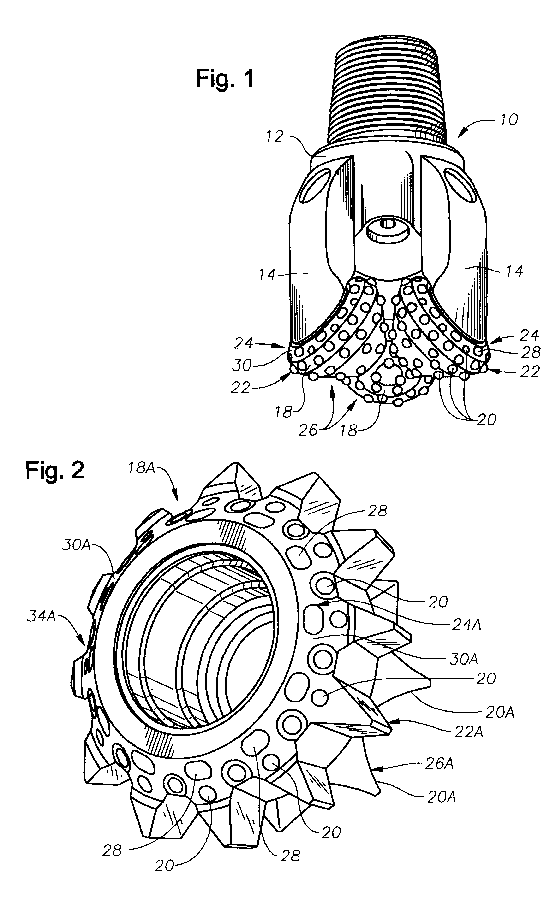
A perspective view of an insert type rolling cutter drill bit 10 of the present invention is shown in FIG. 1. The rolling cutter drill bit 10 includes a body member 12, and a plurality of downwardly extending legs 14 upon which are rotatably mounted a plurality of rolling cone cutters 18.

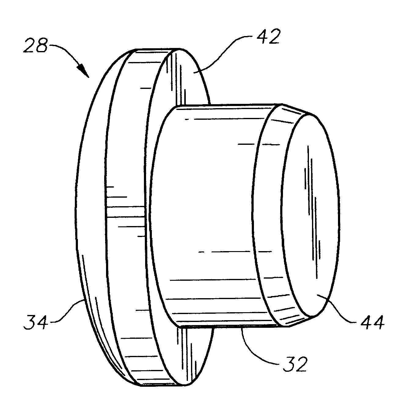
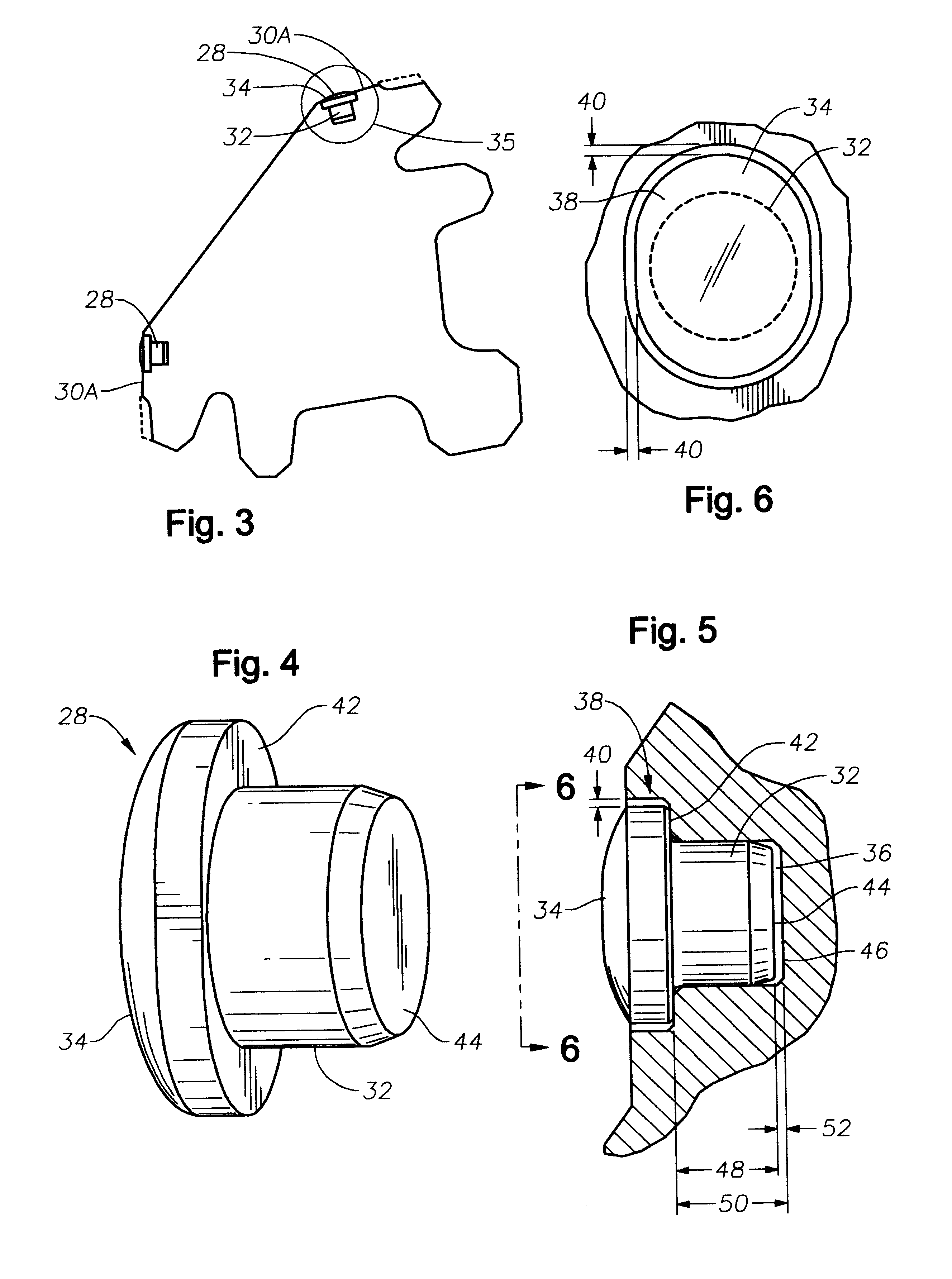
Each rolling cone cutter 18 supports a plurality of cutting inserts 20 which are fitted into sockets formed into the surfaces of the cutters 18. Cutting inserts 20 will preferably be formed of a hard, wear resistant material such as tungsten carbide adapted to cut an earthen formation. The inserts 20 are typically arranged in a plurality of rows. The gauge rows are indicated generally at 22, gauge reaming rows are indicated at 24, and the inner rows are indicated generally at 26. The non-circular cutting inserts 28 of the present invention are shown fitted into a gauge reaming row 24.

Shown in FIG. 2 is an alternate form of rolling cutter 18A. This cutter 18A is used on a type of drill bit known as a...


PUM


Abstract

Disclosed is a wear resistant cutting insert for use in rolling cutter drill bits. The insert has a cylindrical shank that is readily fitted in an interfering manner into cylindrical sockets formed in the rolling cutter. The surface of die insert that engages the formation, however, is none-circular, and preferably, oval shaped. To prevent the insert from turning in the socket, a shallow counterbore is formed about the socket that accommodates the shape of the top, non-cylindrical portion of the insert. The depth of the recess is made slightly greater than the length of the shank of the insert so that the load applied to insert during operation is not transmitted through the shank to the bottom of the socket in the cutter.

Description

1. Field of the InventionThe invention relates generally to rolling cutter earth boring drill bits used for the exploration and retrieval of petroleum and other minerals from the earth. In particular, the invention is a new form of cutting insert that allows a higher percentage of wear resistant material on the gauge face of the cutter of a rolling cutter earth boring drill bit than previously had been practically possible.2. Description of the Related ArtThe practice of horizontal drilling has had a major impact on modern rolling cutter rock bits. Not only are the bearing systems in these bits challenged in horizontal drilling, the cutting structures, particularly the gauge cutting elements, are severely stressed.In order to improve the useful life of the gauge cutting elements, the practice of placing multiple rows of gauge reaming inserts on the gauge faces of the rolling cutters has become commonplace. The inserts are usually arranged such that they utilize the maximum amount of...

Claims


Application Information

Patent Timeline
Patent Type & Authority Patents(United States)
IPC IPC(8): E21B17/00E21B17/10E21B10/56E21B10/50E21B10/08E21B10/46E21B10/567
CPCE21B10/08E21B17/1092E21B10/567E21B10/50E21B10/5673
Inventor SKYLES, LANE P.CARWILE, BILLY L.MAY, WILLIAM L.
Owner REEDHYCALOG LP
Why Eureka
Try Eureka