Fixing clip

a technology of fixing clips and clips, applied in the field of plastic material clips, can solve the problems of large amount of labor time required to perform such fixing by means of add-on elements, and achieve the effect of reducing the drawbacks of known clips

Inactive Publication Date: 2002-05-28
MOLLERTECH SA
View PDF16 Cites 89 Cited by
  • Summary
  • Abstract
  • Description
  • Claims
  • Application Information

AI Technical Summary

Benefits of technology

An object of the present invention is to mitigate the drawbacks of known clips an

Problems solved by technology

Although that kind of assembly is easy to disassemble, it is expensive because it leads to additional tooling bei

Method used


Image

  • Fixing clip
  • Fixing clip
  • Fixing clip

Examples


Embodiment Construction

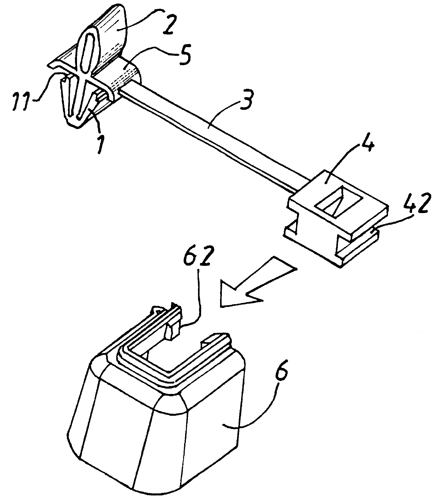
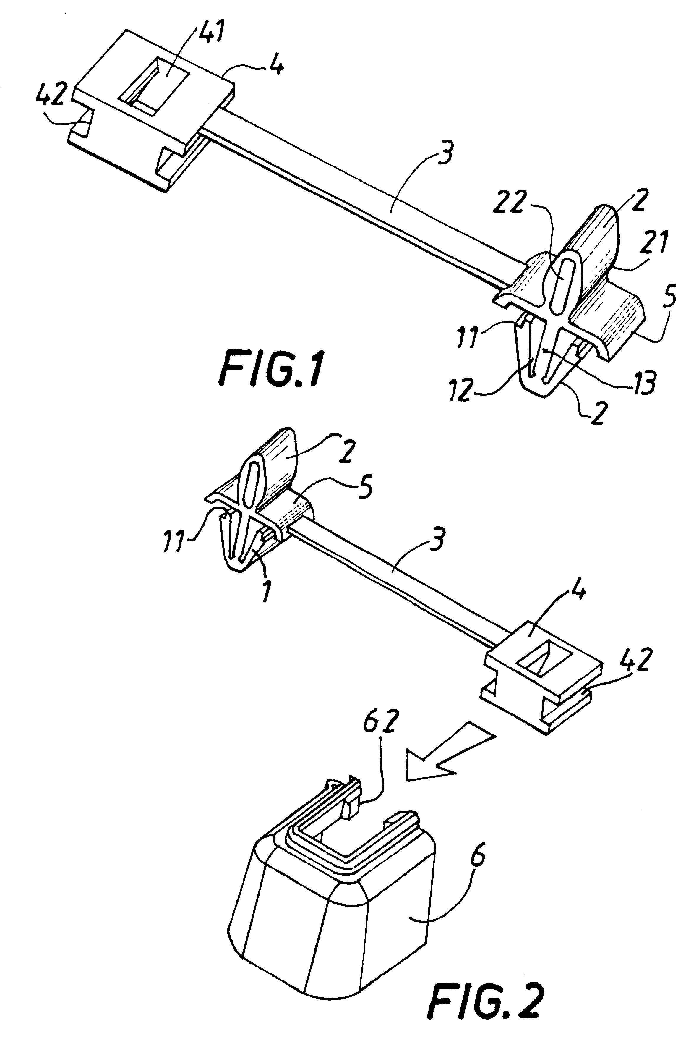
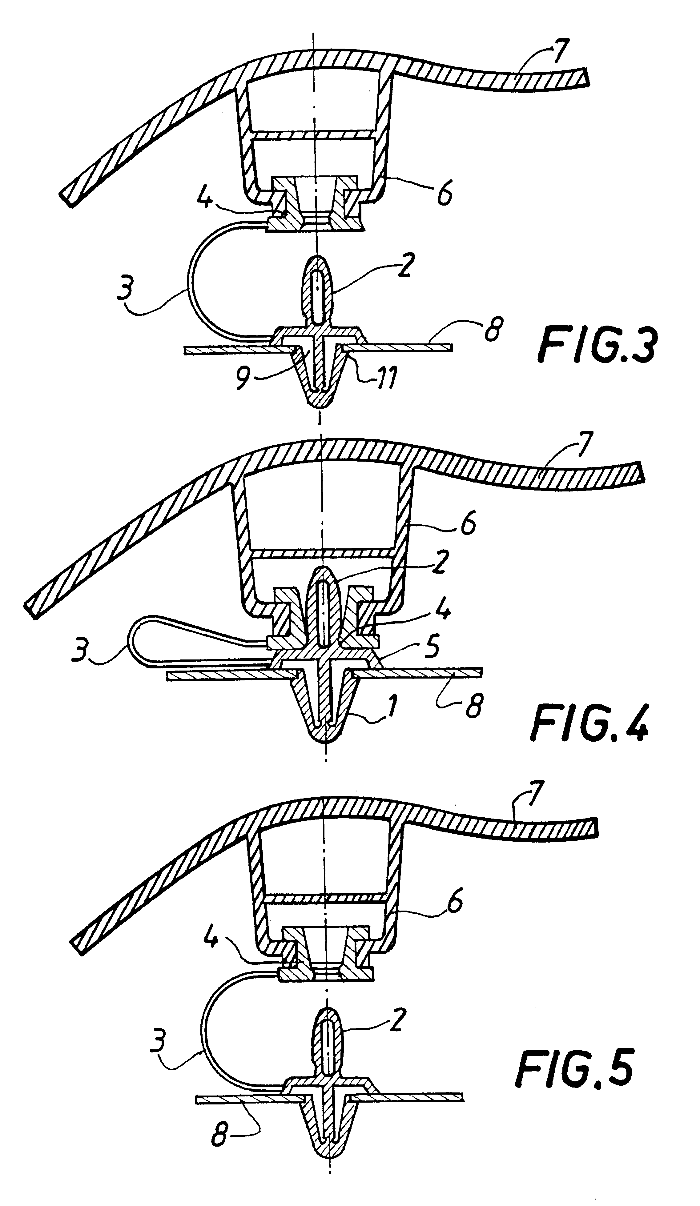
In FIGS. 1 to 5, the same references designate the same elements. In FIG. 1, there can be seen a clip which is injected-molded out of a plastics material and which comprises a base 5 from which a first portion 1 projects downwards for the purpose of being snap-fastened in an opening in bodywork. In the example shown, this portion is anchor-shaped, comprising a shank 13 having two walls 12 projecting in a V-shape from its free end, which walls are moved towards each other during insertion through a hole and then return to their original shape after they have passed through the hole. The free ends of the walls 12 have snap-fastening tips 11 which come into contact with the edges of the hole or opening so as to provide good resistance to extraction.

Starting from the base and in line with the shank 13, there projects a second portion 2 that is generally oval in shape, being made up of two walls 21 which together form an axially-extending hole 22, thereby giving this portion a certain am...


PUM


Abstract

A clip for fixing trim on a support comprises a first male portion suitable for being snap-fastened in an opening of the support and connected by a strap to a female piece that is suitable for snap-fastening on a second male portion of the clip, a piece being suitable for being assembled on the piece by sliding.

Description

The present invention relates to a fastening clip intended particularly, but not exclusively, for fastening pieces made of thermoplastic material and provided with such clips onto metal pieces, particularly in vehicle construction, for the purpose of fixing plastic internal trim onto bodywork.Traditionally, such fasteners are made by means of discrete add-on elements such as rivets, plastics clips, or screws where the thread is engaged in a hole or an opening in the metal or plastics support and where the head holds captive the plastics piece that is to be secured. Although that kind of assembly is easy to disassemble, it is expensive because it leads to additional tooling being made. Furthermore, a large amount of labor time is required to perform such fixing by means of add-on elements.When the inside of a car is fitted with a lateral air bag for the head, it is necessary to retain the interior trim after the bag has inflated so that the trim does not constitute a projectile which...

Claims


Application Information

Patent Timeline
IPC IPC(8): F16B21/08F16B21/00F16B5/06B60R21/216F16B41/00
CPCB60R21/216F16B5/065F16B21/082F16B5/0657Y10T403/7176
Inventor CHAUSSET, FRANCOIS
Owner MOLLERTECH SA
Why Eureka
Try Eureka