Surface light source device of side light type

a surface light source and light source technology, applied in mechanical devices, lighting and heating devices, instruments, etc., can solve the problems of degrading the quality of the display screen, affecting the thickness distribution of the air layer, etc., and achieve the effect of avoiding the reduction of illumination light quality

Inactive Publication Date: 2002-05-28
ENPLAS CORP +1
View PDF6 Cites 25 Cited by
  • Summary
  • Abstract
  • Description
  • Claims
  • Application Information

AI Technical Summary

Benefits of technology

The aim of the present invention is to resolve the above problems of the prior art. The object of the present invention is to provide a side light type surface light source device that can prevent adhesion of a light control member such as a prism sheet to the emitting surface, thereby avoiding reduction in illumination light quality.
The adhesion prevention means applied to the light control member is embodied as providing the light control member with projections having various heights, thereby effectively avoiding the light control member from adhesion.
In accordance with this invention, the roughness of the emitting surface holds diffusion of emitted light to within a range that is small enough for practical purposes, maintaining the directivity of the emitted light. Providing such a roughness on the emitting surface effectively prevents adhesion by lowering the affinity between the light control member and the emitting surface.
A light control member with projections of various heights causes the space between each projection and the emitting surface to vary accordingly. The result is that affinity between light control member and emitting surface is lowered, effectively preventing adhesion. This technique does not reduce emitted light directivity.

Problems solved by technology

This results in disturbances in the thickness distribution of the air layer, thereby providing the pattern appearance.
Further, when applied to a liquid-crystal display backlighting arrangement, it degrades the quality of the display screen.

Method used


Image

  • Surface light source device of side light type
  • Surface light source device of side light type
  • Surface light source device of side light type

Examples


first embodiment

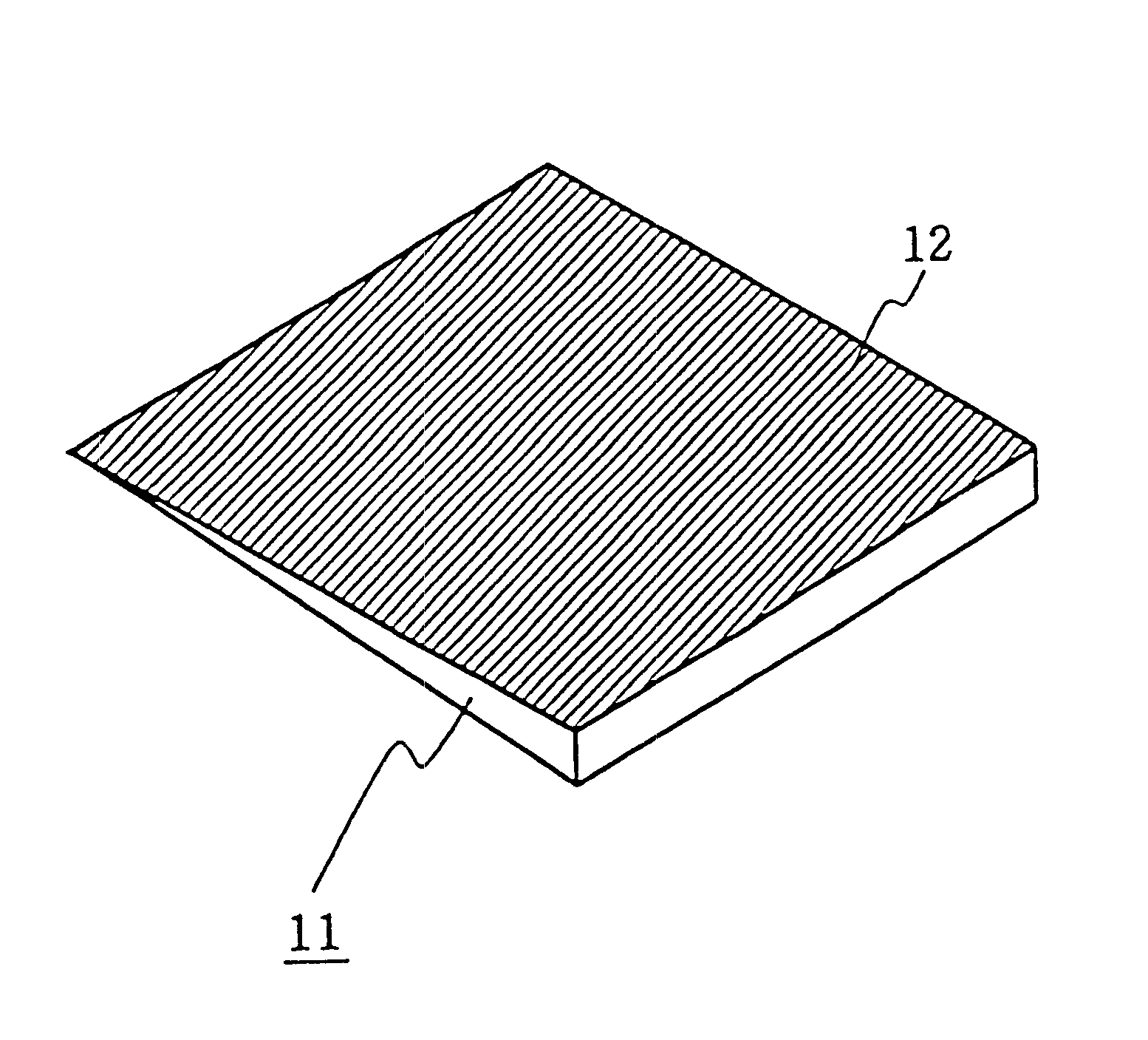
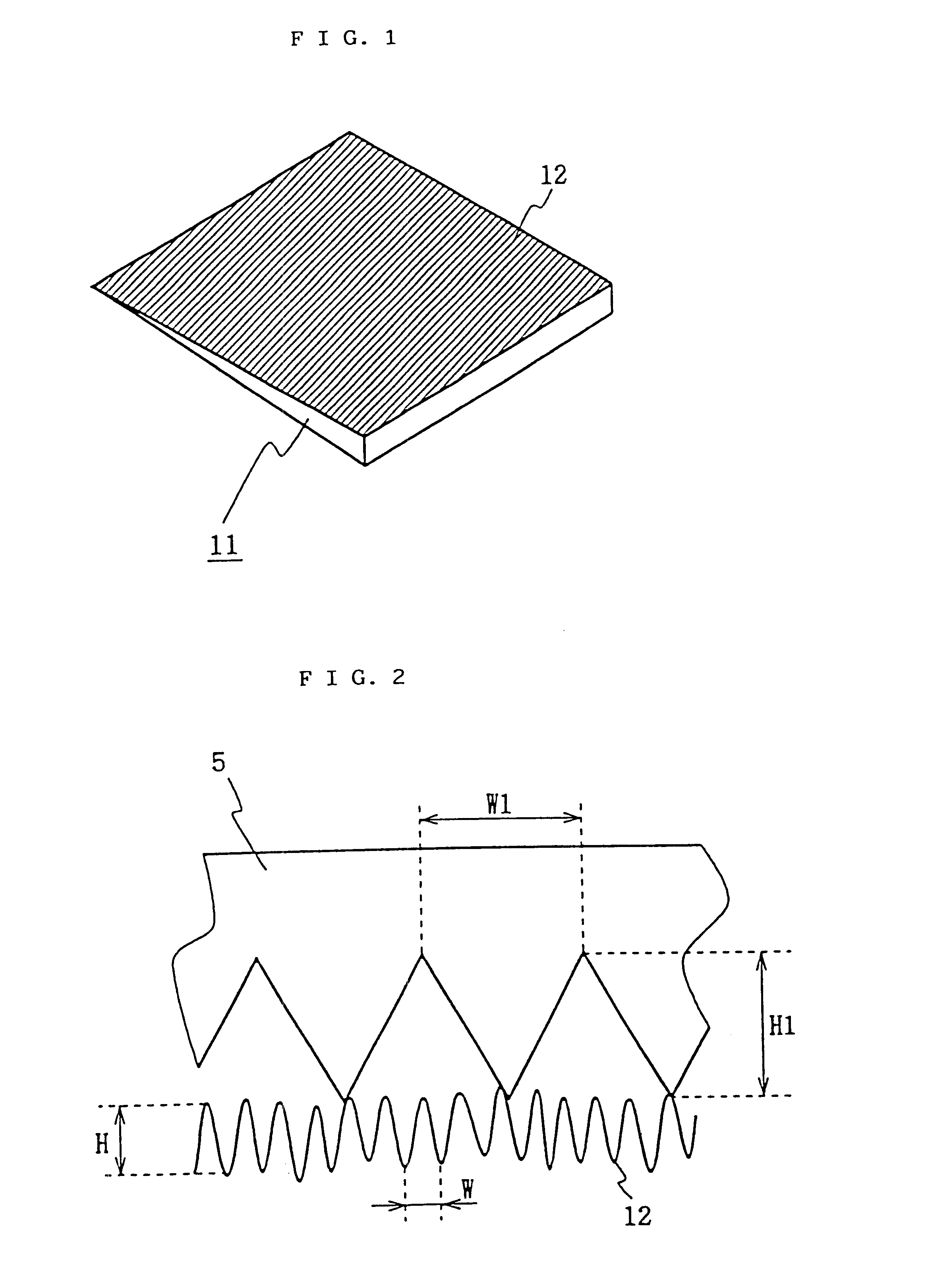
FIG. 1 is a perspective view of a light scattering guide plate used in a side light type surface light source device according to the first embodiment of the present invention. Except for the light scattering guide plate 11, this side light type surface light source device is the same as the side light type surface light source device described with reference to FIGS. 6 and 7, repeated explanation being omitted.

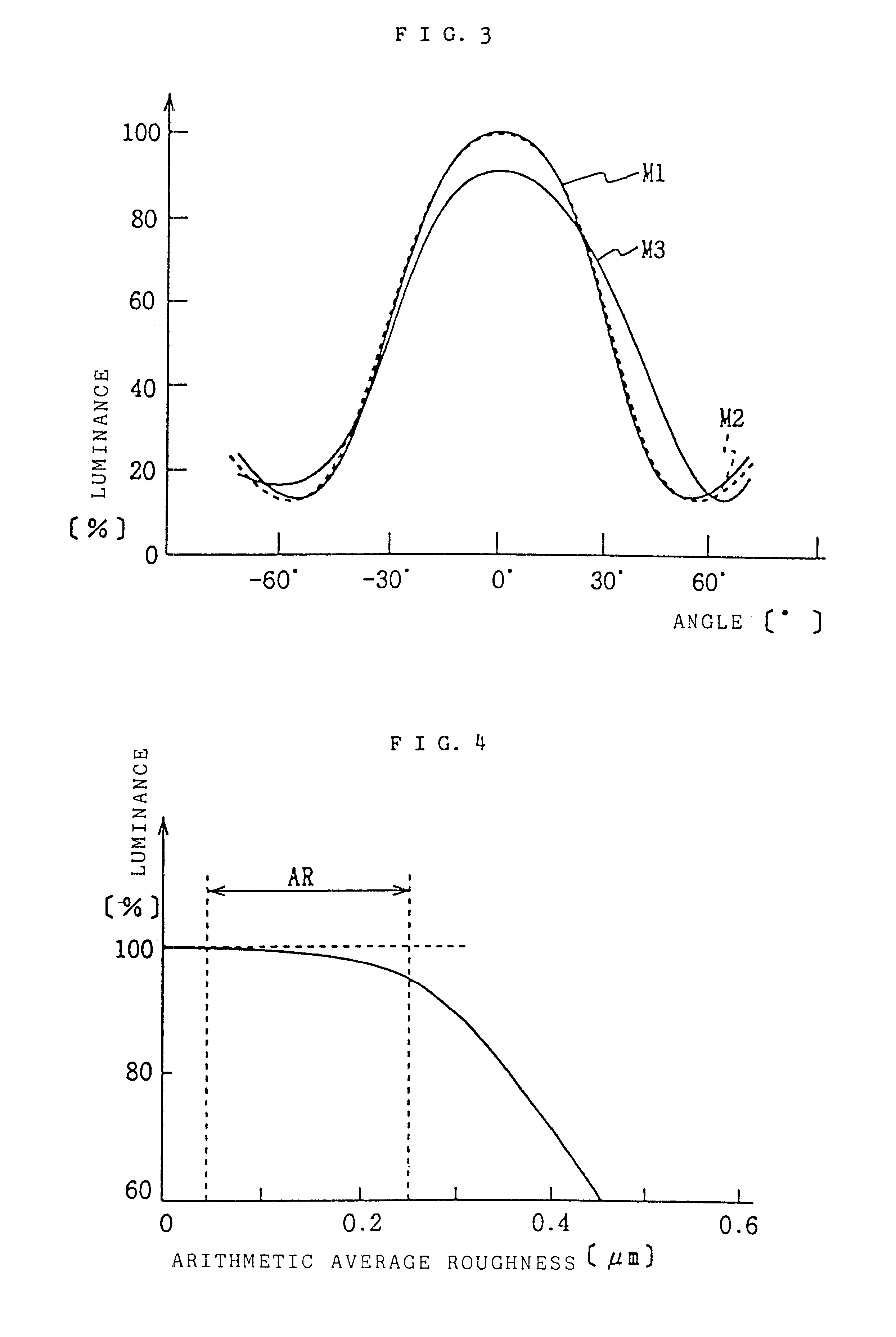
With reference to FIG. 1, emitting surface 12 of the light scattering guide plate 11 is provided with a matt surface (granular surface) formed by mattprocessing. The arithmetic average roughness Ra of the emitting surface (matt surface) 12 is within the range from 0.02 to 0.25 .mu.m. Arithmetic average roughness Ra is a unit of surface roughness specified by JIS B0031-1994.

The roughness imparted to emitting surface 12 effectively prevents the prism sheet 5 disposed closely along the emitting surface 12 from adhering to the emitting surface 12.

FIG. 2 is an enlarged cross-secti...

second embodiment

FIG. 5 is an enlarged cross-sectional view of the emitting surface of a side light type surface light source device according to the second embodiment of the invention. Except for the prism sheet 15 as a light control member, this side light type surface light source device is the same as the side light type surface light source device described with reference to FIGS. 6 and 7, repeated explanation being omitted.

With reference to FIG. 5, the prism sheet 15 is formed of polycarbonate and is provided with numerous rows of projections having a triangular cross-section. It should be noted that height variation is given to these projections. This non-uniformity lowers the affinity (tendency to adhere) between prism sheet 15 and emitting surface 12, effectively preventing adhesion of the prism sheet 15 to the emitting surface without lowering the directivity of the scattering light.

The height variation of the projections on the prism sheet 15 may be based on a non-regular height distribut...


PUM

PropertyMeasurementUnit
arithmetic average roughness Raaaaaaaaaaa
roughness Raaaaaaaaaaa
arithmetic average roughnessaaaaaaaaaa

Abstract

A light control member formed by a prism sheet 5 is arranged along an emitting surface 12 of a light guide plate of a side light type surface light source device for liquid-crystal display backlighting arrangement and the like. The prism sheet 5 is provided with numerous projections formed with a height H1 at a pitch W1 D1. Roughness is imparted to the emitting surface 12 by matt-processing or adhesion of fine particles. The roughness is preferably within the arithmetic average roughness Ra range 0.02-0.25 mum. Non-uniformity may be applied to height H1 of the prism sheet 5. The tendency of the prism sheet to adhere to the emitting surface is reduced and degradation of light quality prevented by the roughness of the emitting surface and / or non-uniform height of projections on the prism sheet.

Description

1. Field of InventionThe present invention relates to a side light type light source device for use with a liquid-crystal display or the like, and more particularly to a side light type surface light source device that employs a light guide plate having emitting directivity.2. Related ArtSide light type surface light source devices have a thin structure and have previously have been applied to backlighting of liquid-crystal display panels and the like.A side light type surface light source device is equipped with a light guide plate, and a rod-shaped light source (primary light source) such as a cold-cathode tube arranged along an edge of the light guide plate. Light emitted by the primary light source is introduced through an edge of the light guide plate into the light guide plate. The light introduced into the light guide plate is deflected and output from one face of the light guide plate to illuminate, for example, a liquid-crystal panel.Light guide plates employed in side ligh...

Claims


Application Information

Patent Timeline
Patent Type & Authority Patents(United States)
IPC IPC(8): F21V8/00G02B5/04G02B6/00G02B27/00G02F1/1335G02F1/13357
CPCG02B5/045G02B6/0053G02B6/0036
Inventor ISHIKAWA, TSUYOSHINOGUCHI, NOBUHISA
Owner ENPLAS CORP
Why Eureka
Try Eureka