Bag dispenser

a bag dispenser and bag technology, applied in the field of bag dispensers, can solve the problem of difficult opening of bags,

Inactive Publication Date: 2002-06-04
ARMY U S ARMY CORPS OF ENGINEERS AS REPRESENTED BY TH SEC OF THE +1
View PDF12 Cites 12 Cited by
  • Summary
  • Abstract
  • Description
  • Claims
  • Application Information

AI Technical Summary

Benefits of technology

In another embodiment, the central tab is tapered such that the tab is increasingly wider below each successive bag. It is thus possible to assure that the weakest point on the central plastic tab is always

Problems solved by technology

The edges of the bag openings frequently stick t

Method used


Image

  • Bag dispenser
  • Bag dispenser
  • Bag dispenser

Examples


first embodiment

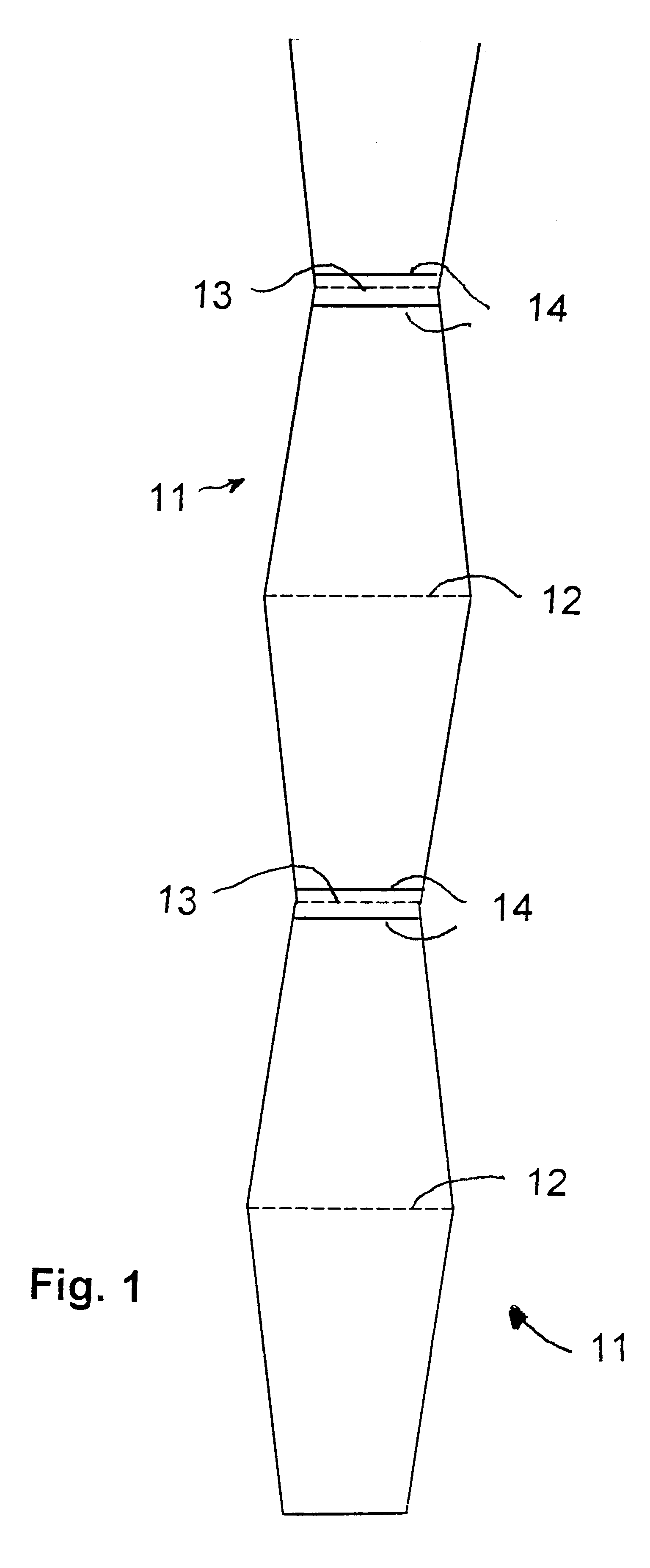
The bag dispensers of this invention overcome the inconvenience of prior art bag dispensing means and methods in several ways. In a first embodiment, means are provided for dispensing bags, one at a time, comprising a roll of bags attached to one another along either their tops or bottoms. The top of a first bag is attached to the top of the second next adjacent bag, followed by the bottom of said second bag attached to the bottom of a third next adjacent bag, in a continual alternating fashion forming a roll wherein the width of the top-to-top connection is greater than the width of the bottom-to-bottom connection, and wherein the top connections between adjacent two bags each has a row of closely-spaced perforations, and wherein the bottom connections between two adjacent bags each has a seam closing each bag at its bottom end, and a row of closely-spaced perforations between the seams of adjacent bags, whereby a bag is separated from the roll by pulling and tearing along the row ...

second embodiment

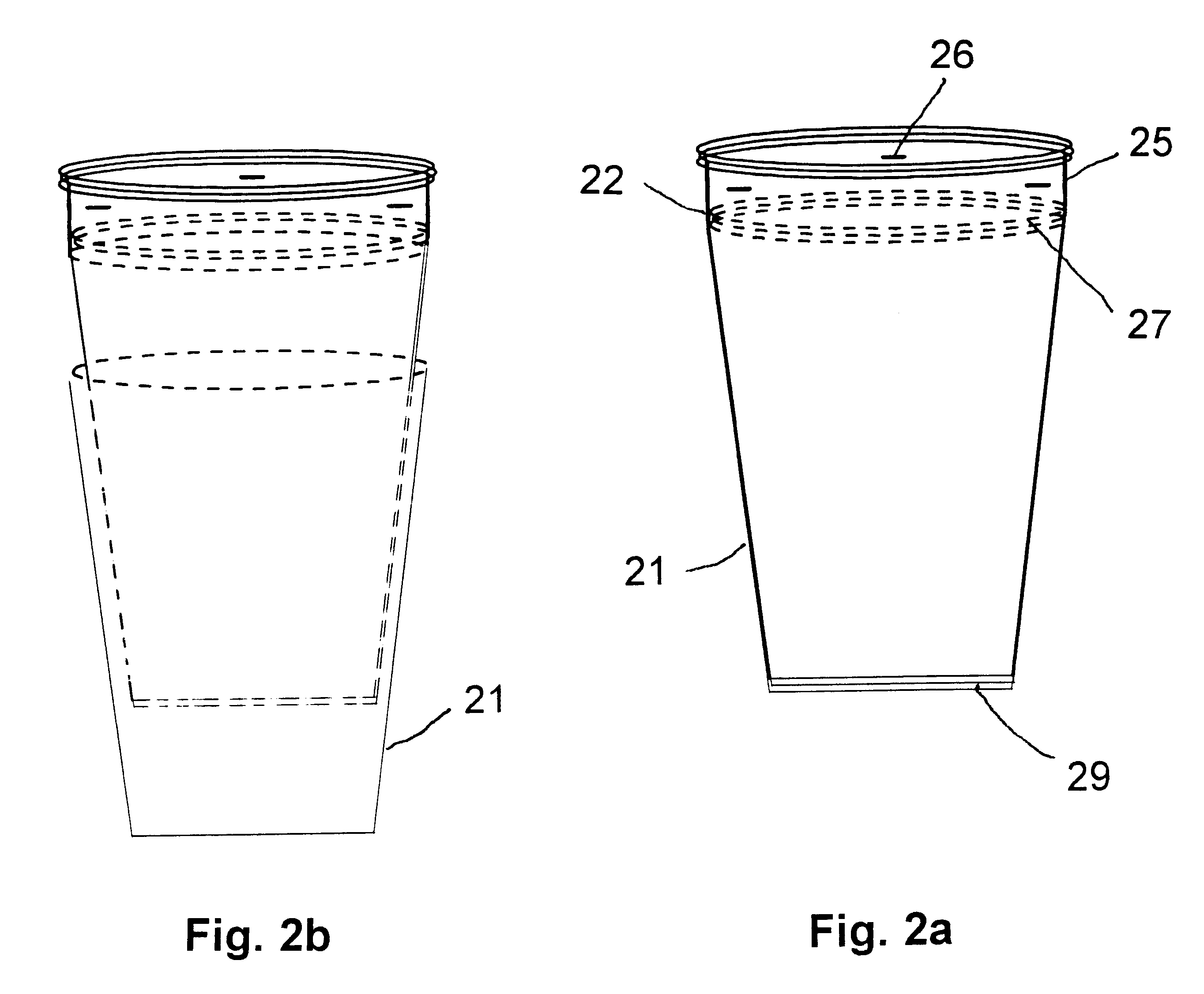
In this invention, a plurality of tapered bags is nested, with one bag inside the next. The bags are tapered at both sides, such that they are narrower along their bottom edges and wider across their top edges. At their tops, they are each individually attached to strips which are circumferential extensions of the tops and which in turn are attached to each other by conventional means such as staples. Rows of closely-spaced perforations below the strips ensure that each bag is open when separated from the strips by pulling and tearing along the row of perforations.

With reference to FIG. 2a, tapered bags 21, each having a top opening 22 and a sealed bottom 29, nested with one bag inside the next, of which the openings 22 are removably attached to strips 25, which in turn are fastened to each other by staples 26. The strips 25 are extensions of bag openings 22 and have sufficient width to enable a stack of strips to be fastened together when assembled. Rows of perforations 27 adjacent...

third embodiment

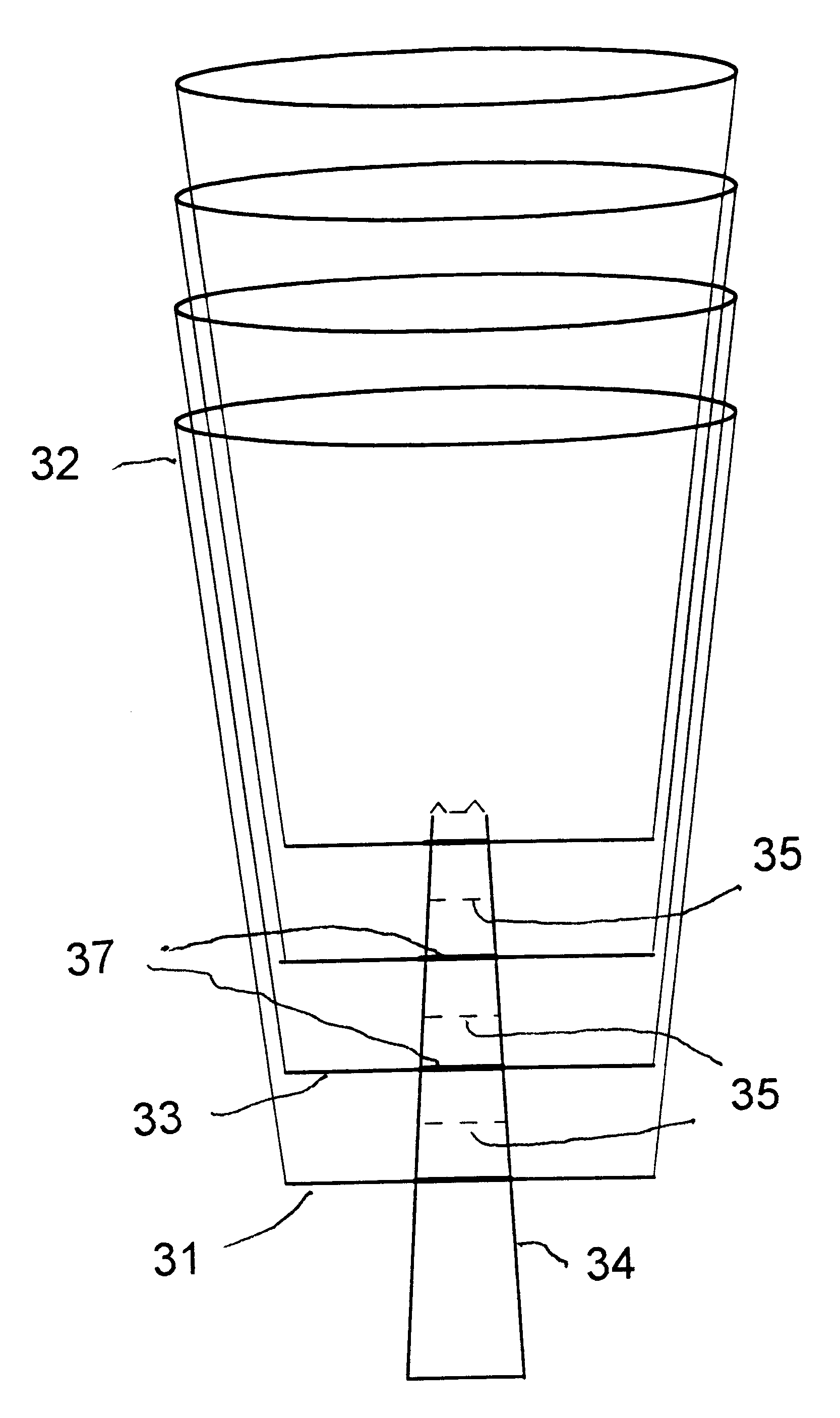
In this invention, means are provided for dispensing bags, one at a time, comprising a plurality of bags, one nested within a next adjacent bag, and further comprising a central tab passing through said bags and being attached to a bottom seam of said bags, and transverse rows of perforations in the tab between adjacent points of attachment of the bags and the tab, and means for attaching the bags to the tab, and wherein a bag is separated from the tab by pulling and tearing along the row of perforations to provide a bag having an open top end and a closed bottom end.

With reference to FIG. 3, in this third embodiment of the invention, each tapered bag 31 is first manufactured as a tapered tube with the top 32 and bottom 33 of each tube open. A single central tab 34 of plastic, of a width that fits through the bottom 33, is perforated transversely at intervals to form rows of closely-spaced perforations 35 that are parallel to each other. The perforated central tab 34 is inserted thr...


PUM


Abstract

Plastic, paper, aluminum foil, or aluminum foil laminated with plastic bags are dispensed, one at a time, from a bag dispenser. In a first embodiment, bags are provided in rolls, connected top-to-top and bottom-to-bottom. Each bag is tapered towards its bottom such that its top-to-top connection with the next bag is wider than the bottom-to-bottom connection. Each bottom-to-bottom connection has sealed seams, which ensure that the bags are closed at their bottoms, and a row of closely spaced perforations on a connecting portion between two seams, which allow adjacent bags to be separated by pulling and tearing along the row of perforations. In an alternate embodiment of this invention, a plurality of tapered bags is nested with one bag inside the next adjacent bag. The bags are tapered at both sides such that their bottoms are narrower than their tops. At their tops, they are attached to strips of materials that are in turn attached to each other by conventional means such as staples. Rows of closely spaced perforations ensure that each bag is open when a bag is separated from the strips by pulling and tearing along the row of perforations. In a third embodiment the bags are nested and attached to a perforated central tab that passes through the bottom seam of each bag. The nested arrays of bags may be placed in a funnel-like dispenser that holds the nested bags in an upright position.

Description

I. BACKGROUND OF THE INVENTIONThe invention described herein may be manufactured, licensed, and used by or for governmental purposes without the payment of any royalties thereon.1. Field of the InventionThis invention relates to improved means and methods for dispensing bags, such as plastic, paper, aluminum foil, or aluminum foil laminated with plastic. Specifically, it provides systems for dispensing bags, one at a time, from rolls or from bags stacked in a nested configuration, such that the bags are open after detachment from the dispenser.2. Prior ArtBags, such as paper, plastic, aluminum foil, or aluminum foil laminated with plastic, for packaging of small objects or bulk materials, are typically produced in rolls wherein individual bags are detached from adjoining bags by pulling and thereby separating the bags along rows of small perforations. The bottom of one bag is typically adjacent to the top of the next bag in the roll. The edges of the bag openings frequently stick to...

Claims


Application Information

Patent Timeline
IPC IPC(8): B65D33/00
CPCB65D33/002B65D33/001
Inventor SMITH, DENNIS RAYWEISS, JR., CHARLES ARTHURMALONE, PHILIP GARCIN
Owner ARMY U S ARMY CORPS OF ENGINEERS AS REPRESENTED BY TH SEC OF THE
Why Eureka
Try Eureka