
Anti-theft device for motor vehicles

a technology for anti-theft devices and motor vehicles, which is applied in the direction of anti-theft devices, anti-theft cycle devices, instruments, etc., can solve the problems of inhibiting the operation of motor vehicles, unable to drive the vehicles a substantial distance, and unable to so as to reduce the premium, prevent theft of unattended vehicles, and easy to attach to motor vehicles

Inactive Publication Date: 2002-06-04
WINNER INT ROYALTY
View PDF9 Cites 26 Cited by
  • Summary
  • Abstract
  • Description
  • Claims
  • Application Information

AI Technical Summary

Benefits of technology

In accordance with the present invention, there is provided an anti-theft device which can be easily attached to a motor vehicle, which device will thwart or hamper hijacking, as well as prevent theft of an unattended vehicle. In accordance with preferred embodiments of the invention, the anti-theft device is a passive system which will be armed and disarmed without physical intervention of the operator owner. This type of system is considered beneficial and premium reducing to some insurance carriers.
Still a further object of the present invention is the provision of a device and method, as defined above, which device and method are somewhat inexpensive, can be universally adapted for a variety of accessories and is easily installed by a Do-It-Yourself person having limited skills and tools.

Problems solved by technology

If the person carrying the PID is physically ejected from the vehicle, the person commandeering the vehicle can not drive the vehicle a substantial distance.
Although this scenario would be unwise and could invite an attempt to steal the vehicle, such attempt would be unsuccessful.
This signal inhibits the operation of the motor vehicle by ultimately disabling the vehicle.

Method used


Image

  • Anti-theft device for motor vehicles
  • Anti-theft device for motor vehicles
  • Anti-theft device for motor vehicles

Examples


Embodiment Construction

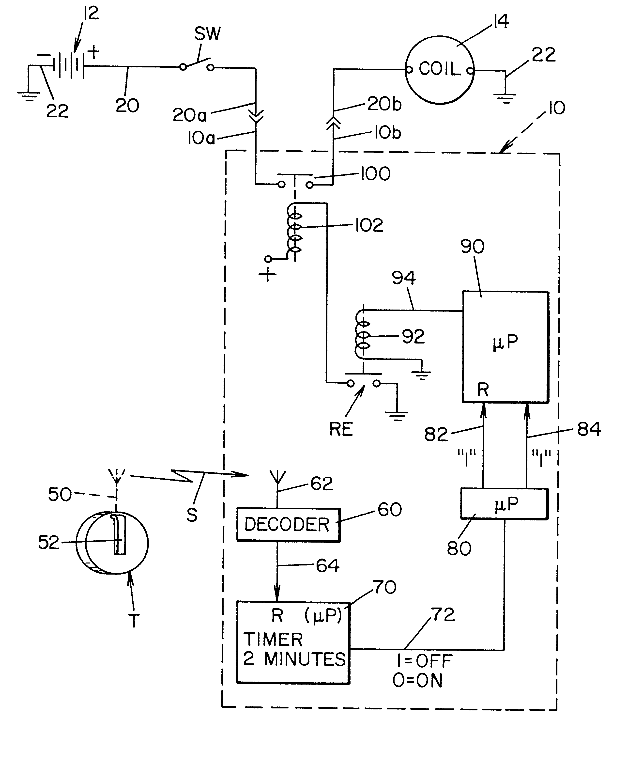
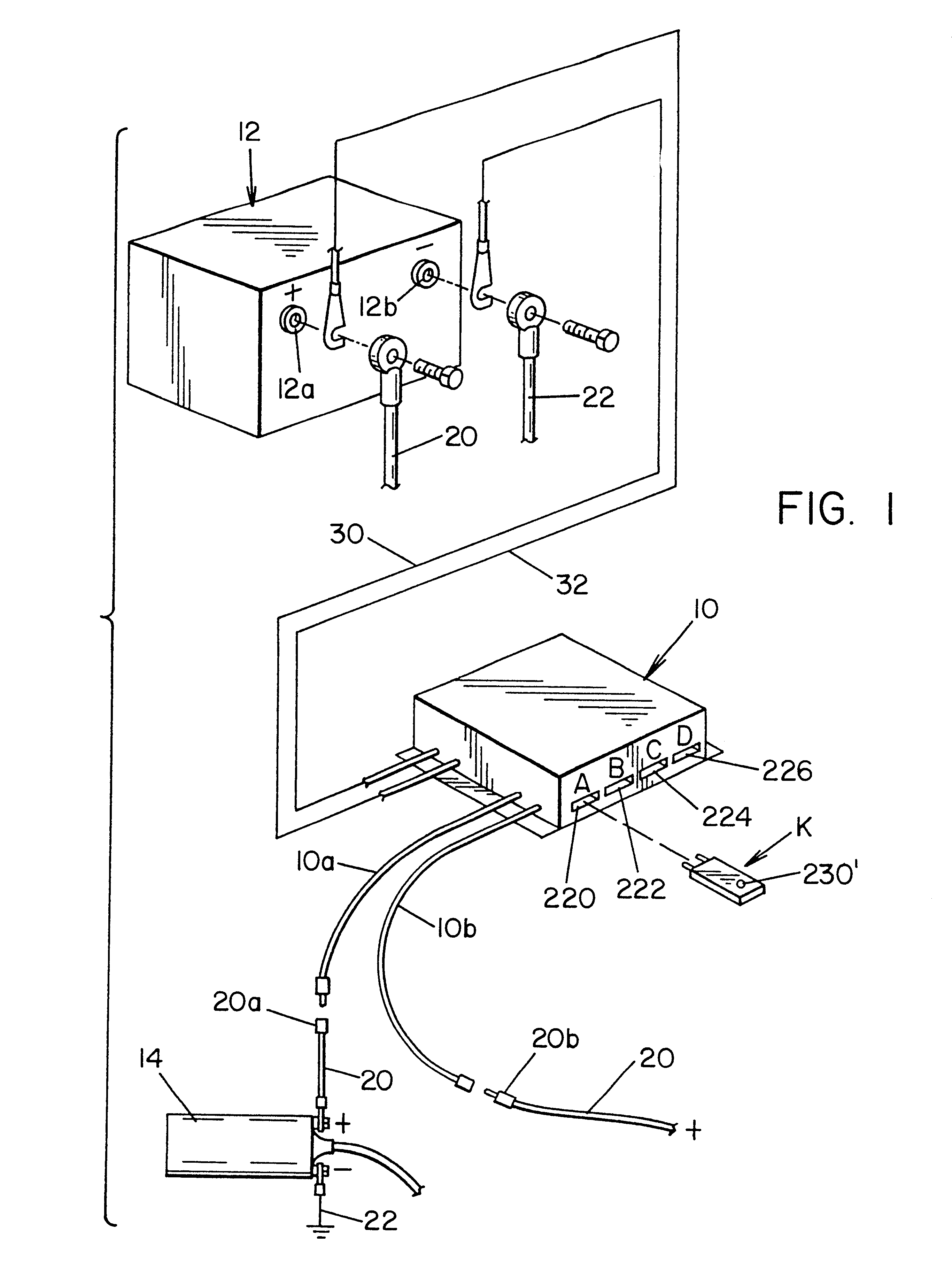
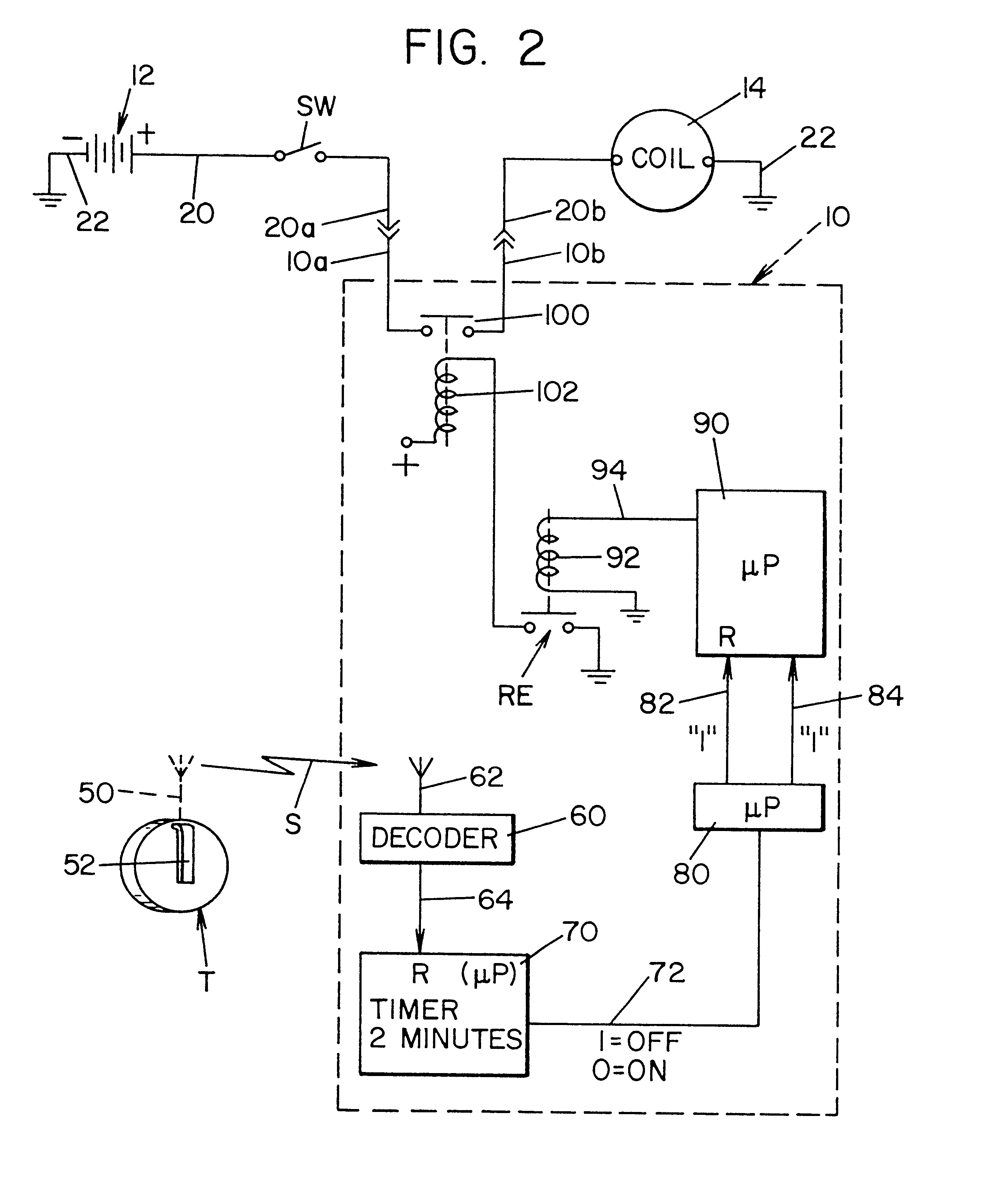
Referring now to the drawings wherein the showings are for the purpose of illustrating a preferred embodiment of the invention only and not for the purpose of limiting same, FIG. 1 illustrates a connection of the preferred embodiment of the present invention wherein. the anti-theft control unit 10 is connected in a system including a standard motor vehicle battery 12 and an ignition coil 14. Battery cables 20, 22 provide power to coil 14 for the purpose of operating the motor vehicle. As is known, when coil 14 is inoperative, the internal combustion engine powering the motor vehicle will be rendered inoperative. In accordance with the preferred embodiment of the present invention, control unit 10 includes a microprocessor and is powered by leads 30, 32 form standard battery 12. Connection of control unit 10 on a motor vehicle includes mounting the unit by bolts in an inaccessible location. The battery cable 20 is then cut adjacent coil 14 to provide spaced ends 20a, 20b. These space...


PUM


Abstract

An anti-theft device for a motor vehicle wherein a personal identification unit is carried by an authorized operator of said motor vehicle and includes means for identifying its location in the vicinity of the motor vehicle. A vehicle control unit mounted onto the motor vehicle, has a first and second condition with means for allowing operation of the motor vehicle when the control unit is in the first condition and means for inhibiting operation of the motor vehicle when said control unit is in the second condition and means for shifting the control unit into the second condition at a time subsequent to removal of the identification device from the vicinity of the motor vehicle and / or upon the occurrence of a predetermined condition of movement of the vehicle subsequent to removal of the identification device from the vicinity of the vehicle.

Description

The present invention relates to the art of anti-theft devices for motor vehicles and more particularly to a device which will thwart attempts by criminal elements to forcibly commandeer a vehicle from an authorized operator.The invention has particular application to preventing the escalating incidences of physical commandeering of motor vehicles occurring primarily in urban areas and it will be described with particular reference thereto; however, the invention has broader applications and is extremely effective in preventing theft of a vehicle after it has been parked by an authorized operator. Also the invention allows programmed operation of accessories associated with the vehicle upon approach and retreat of the authorized operator of the motor vehicle or when the vehicle is parked and unattended. Consequently, it is appreciated that the invention has these broader applications even though particular emphasis is applied to its primary goal of hampering or thwarting commandeeri...

Claims


Application Information

Patent Timeline
Patent Type & Authority Patents(United States)
IPC IPC(8): B60R25/04B60R25/10
CPCB60R25/045B60R25/24B60R25/1003B60R25/10B60R25/31B60W50/08
Inventor WINNER, JR., JAMES E.RUTKOWSKI, JOHN
Owner WINNER INT ROYALTY
Learn More