Torque tool

a torque tool and torque technology, applied in the direction of wrenches, screwdrivers, toothed gearings, etc., can solve the problems of affecting the reliability and service life of these tools, and not being addressed

Inactive Publication Date: 2002-06-11
NEW WORLD TECH
View PDF9 Cites 88 Cited by
  • Summary
  • Abstract
  • Description
  • Claims
  • Application Information

AI Technical Summary

Benefits of technology

The torque tool, conform the present invention, comprises a torque converter actuated by a motor. The torque converter includes a housing incorporating internally, with sequentially decreasing diameters, the following: a threaded bore, an annular indentation, an internal spur gear and a smooth bore; and externally, an external spur or a hexagonal zone. The torque converter further comprises a flange for interconnecting the torque converter with the motor. The torque converter incorporates as well a threaded ring for engaging the threaded bore. The threaded ring is mounted with a close-running feet to a cylindrical extension of the flange and with a sliding contact to a flat surface of the flange. The threaded ring is provided with several axially through-holes circumferentially and equidistantly disposed with respect to the axis of the threaded ring. An index plate, located in the annular indentation, comprises a multiplicity of orifices disposed on a circumference equal to that of the several axially through-holes. Several resiliently biased balls are essentially disposed in the through-holes and partially in a corresponding number of orifices of the multiplicity of orifices. Use is made of fasteners for securing the index plate against the flange.

Problems solved by technology

However, several design problems, which directly influence the reliability and service life of these tools, are not addressed.

Method used


Image

  • Torque tool
  • Torque tool
  • Torque tool

Examples


Embodiment Construction

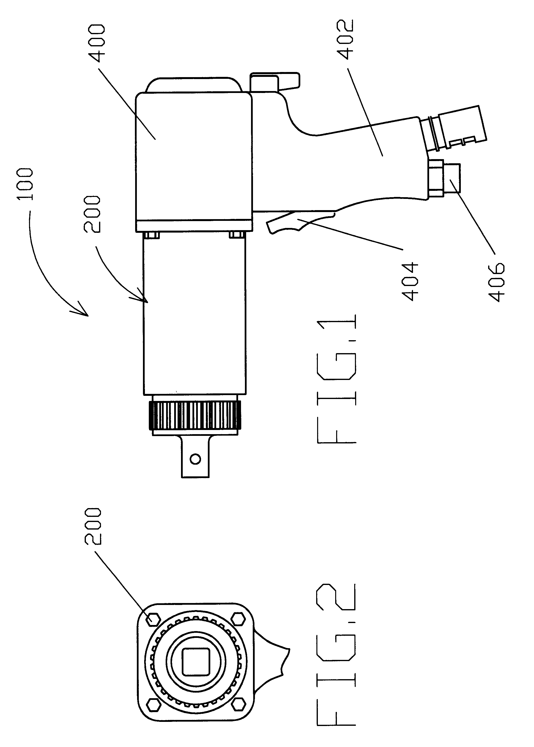
Referring now to the accompanying drawings and more particularly to FIG. 1 thereof, an embodiment of the torque tool of this invention is generally indicated at 100 and has a torque converter 200 actuated by a motor 400. Torque tool 100 of this invention is conveniently employed, but not exclusively, with a pneumatic motor which, in case of breaking of one or more components, will simply stall. A pressure regulated assembly (not shown) connected between a source of compressed air and pneumatic motor 400 is used.

Pneumatic motor 400 is a hand-held motor of conventional design and is provided with a handle 402, a trigger 404 to activate the motor, and a compressed air connection 406.

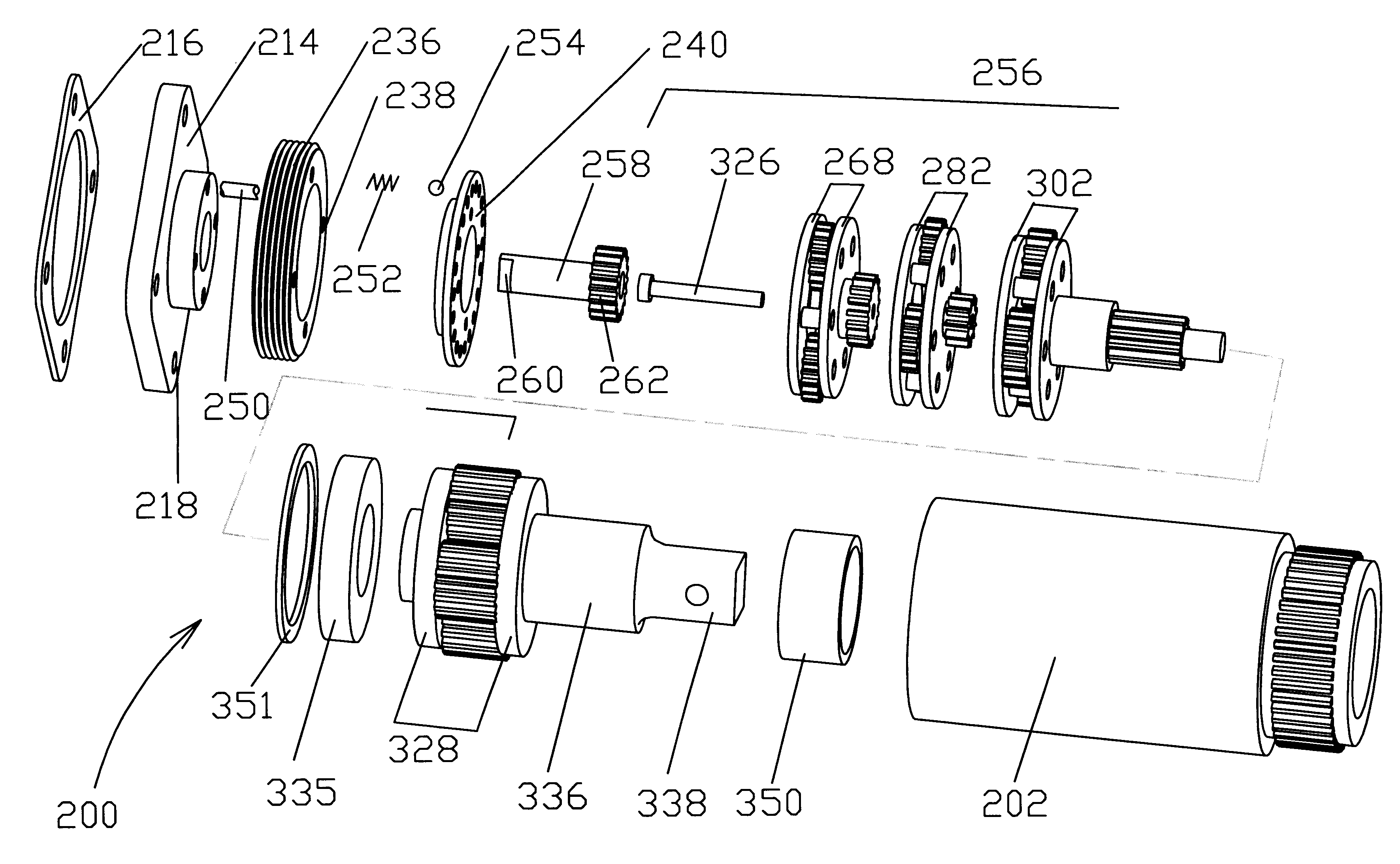
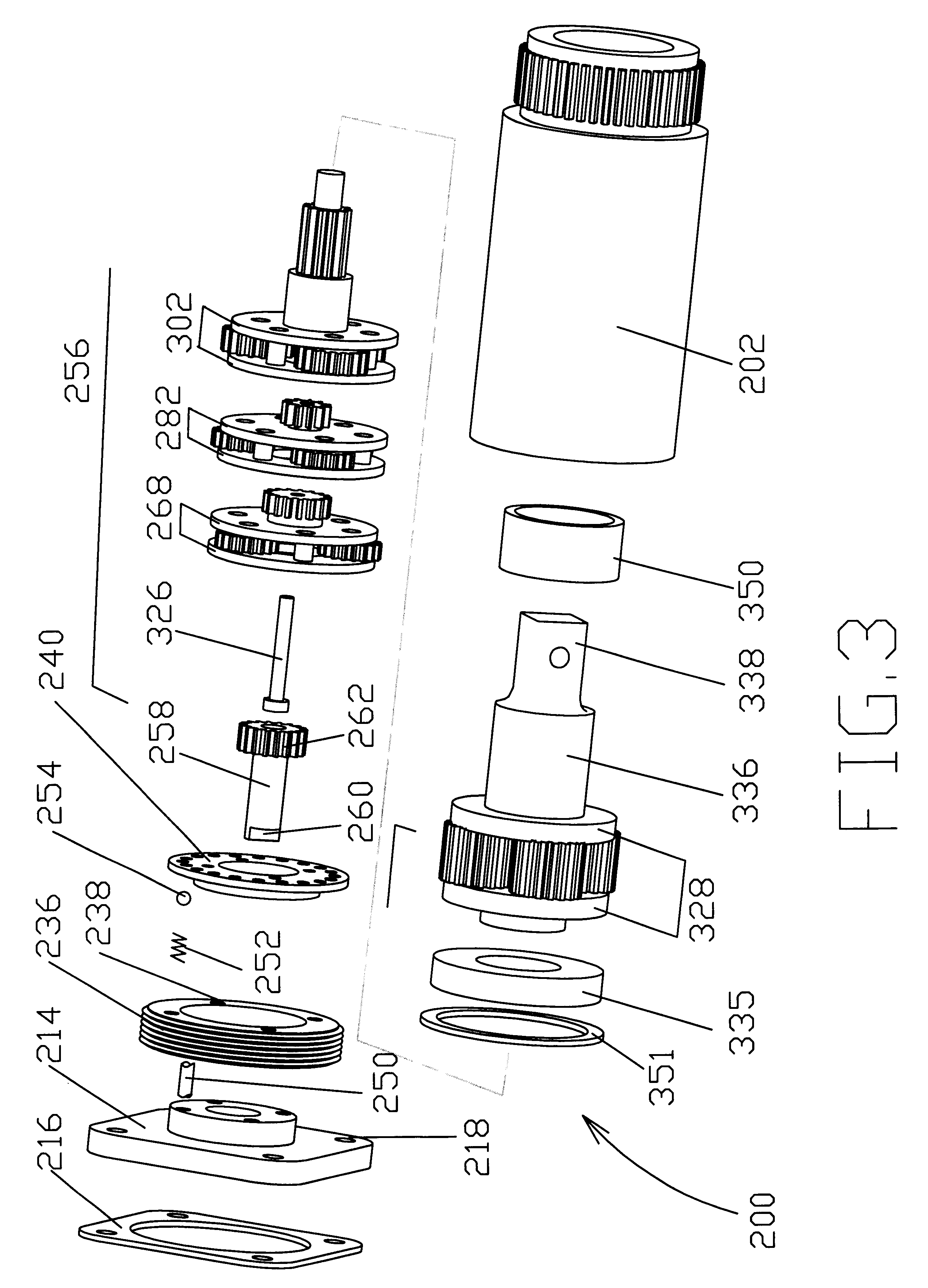
Torque converter 200 is best illustrated in an exploded view in FIG. 2. As shown therein, torque converter 200 comprises a housing 202 of a tubular structure having a threaded bore 204, followed by an annular indentation 205 and then by a spur gear 206 and ending with a smooth bore 208. Threaded bore 204 ha...


PUM


Abstract

The torque tool comprises a torque converter including three planet carriers which encase three planetary gears. Each of the three planetary gears includes a sun gear and three planet pinions. Each of the three planet carriers has an input disc-shaped plate, directed towards an input shaft of the torque tool and an output disc-shaped plate directed towards an output shaft of the torque tool. The input and output shafts constitute the main shafts of the torque tool. Two of the three planet carriers, which are next to the input shaft, have their output disc-shaped plates extending into sun gears with which they form unitary structures. A stepped pin is centrally disposed in a needle bearing of a first sun gear adjacent the input shaft and extends through sliding bearings located in the following sun gears. A first large diameter of the stepped pin is commensurate with an interior diameter of the needle bearing and a second small diameter of the stepped pin is commensurate with interior equal diameters of the sliding bearings inserted in the following sun gears. The planet pinions of one of the three planet gears, which is adjacent to the output gear, arc each provided with a multiplicity of roll needles closely spaced together, the multiplicity of roll needles being inserted between each of the at least three planet gears and an axle for supporting.

Description

I. BACKGROUND OF THE INVENTIONThe present invention relates in general to tightening devices for use in bolt-and-nut fastenings and, more particularly, to a torque tool.Known prior art torque tools, either of the general category of this invention or having specific features of interest, are found in a great number among the U.S. patents. However, several design problems, which directly influence the reliability and service life of these tools, are not addressed.It is a first objective of this invention to design sun gears integrally with one of the disc-shaped plates of planet carrier cages, by this preventing misalignment of the main components and reducing the manufacturing costs.It is a second objective of this invention to enhance the service life of an important subassembly of the torque tool the stepped pin-subassembly, by using, there where the velocity is higher, a larger diameter bearing.It is the third objective of the present invention: to use roll needles characterized ...

Claims


Application Information

Patent Timeline
Patent Type & Authority Patents(United States)
IPC IPC(8): B25B17/02B25B17/00B25B21/00F16H1/46F16H1/28
CPCB25B17/02F16H1/46B25B21/00
Inventor PROVOST, DAN
Owner NEW WORLD TECH
Why Eureka
Try Eureka