Scalable network restoration device

a network restoration and scalable technology, applied in the field of telecommunications networks, can solve the problems of relatively expensive investment of dcs machines for network operators

Inactive Publication Date: 2002-06-11
TELECOMM RES LAB
View PDF28 Cites 30 Cited by
  • Summary
  • Abstract
  • Description
  • Claims
  • Application Information

AI Technical Summary

Problems solved by technology

However, DCS machines continue to be relatively expensive investments for network operators.

Method used


Image

  • Scalable network restoration device
  • Scalable network restoration device
  • Scalable network restoration device

Examples


Embodiment Construction

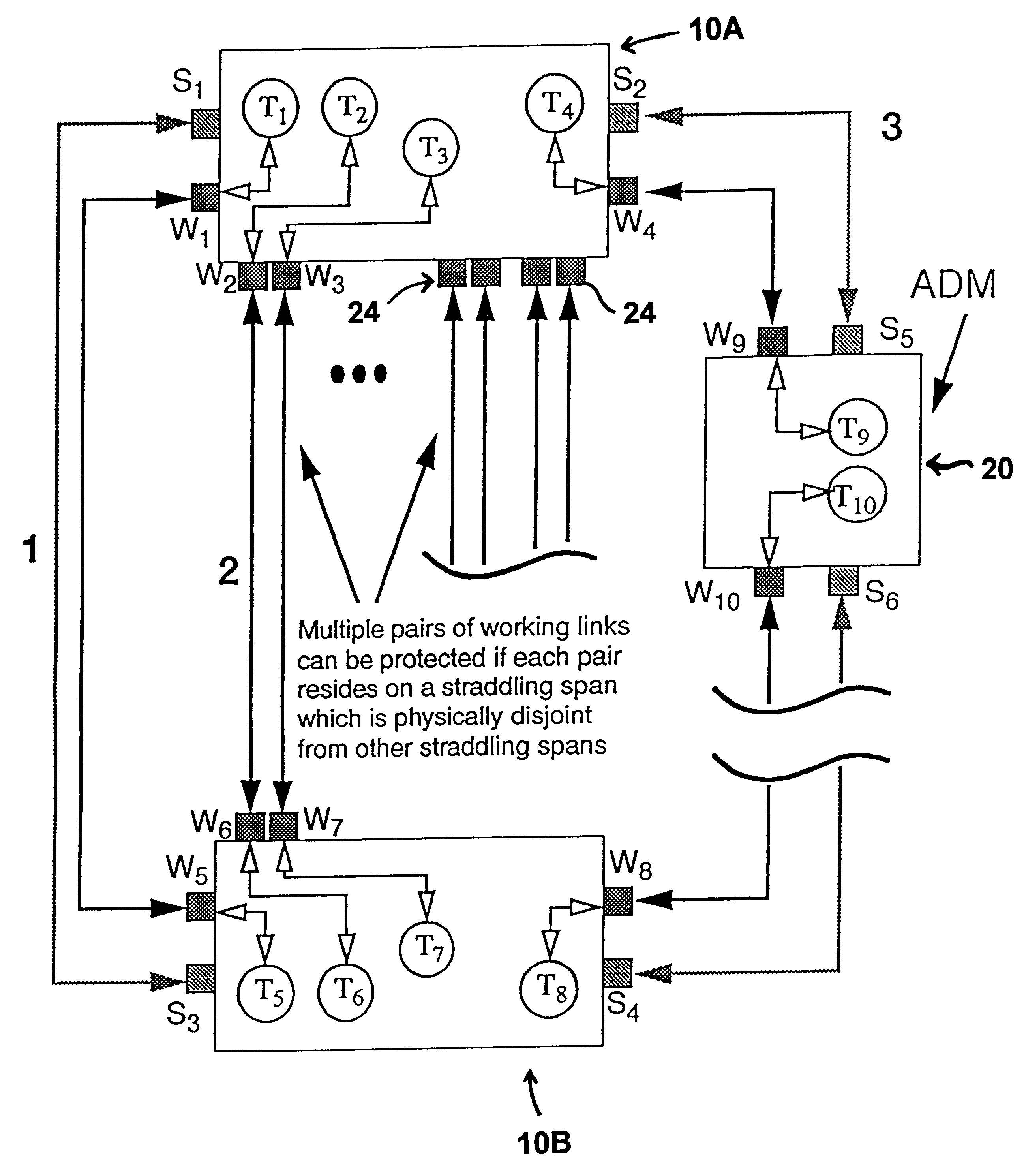
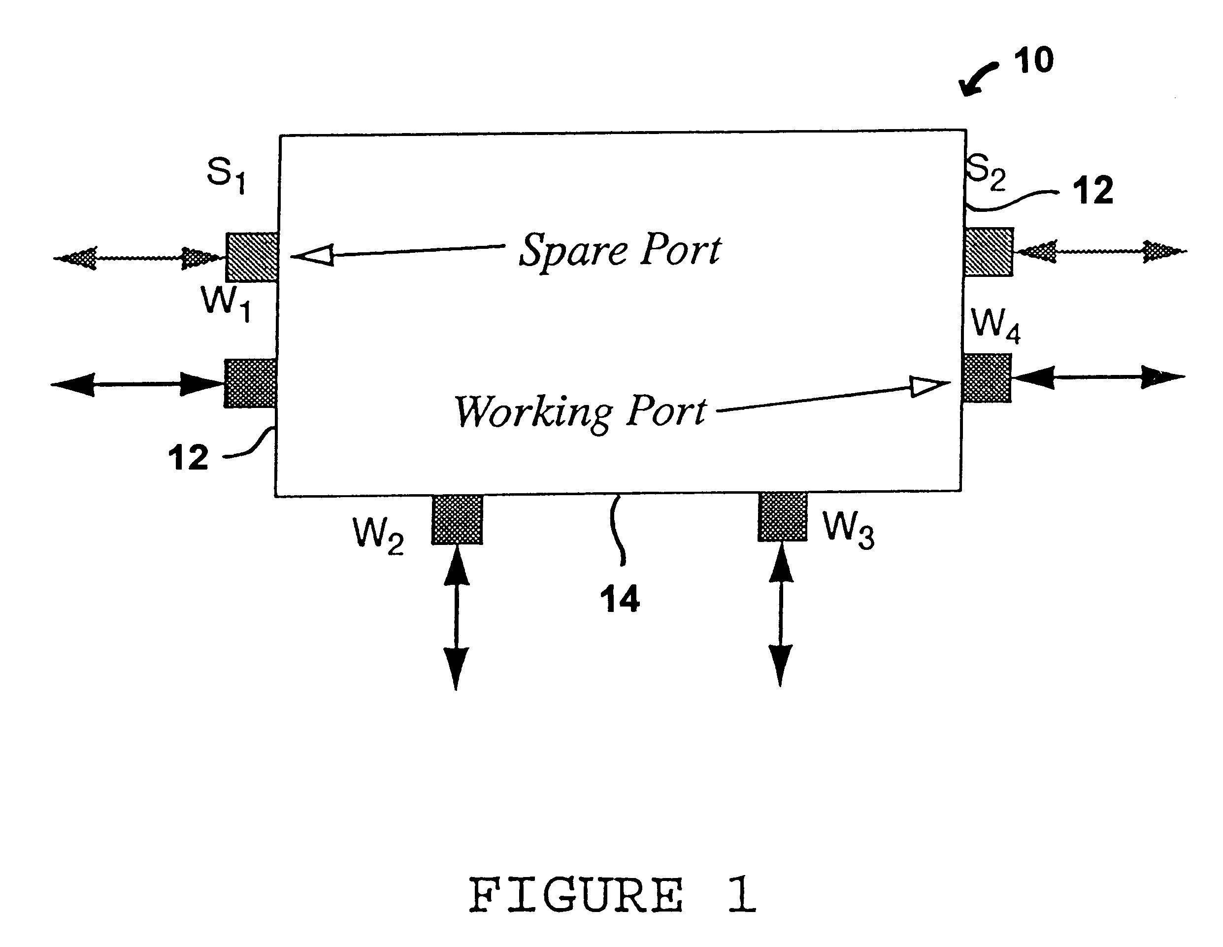
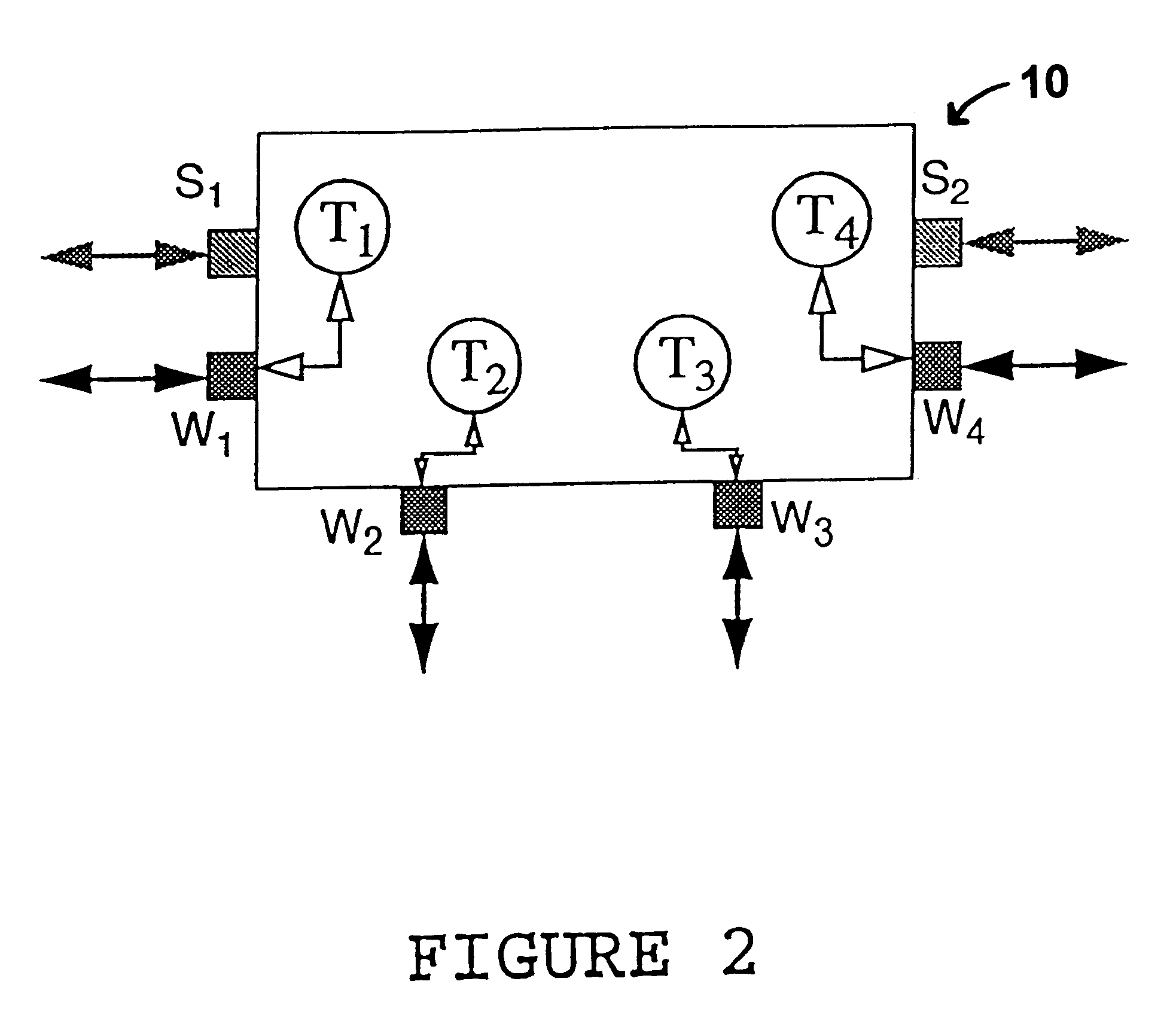
In FIG. 1, S1 is a spare (east) port, S2 is a spare (west) port, W1 is a working (east) port, W2 and W3 are working (south) ports and W4 is a working (west) port. The ports are shown logically separated, but each pair may share a single multiplexed digital signal. For, example each pair (east, west or south) could split the available payload in a single bidirectional OC-48 line. The three "sides" of the device are referred to as East, West and South (North being omitted but would be a placeholder for the local input / output access to working signals). These names are really, more generally, the designations of particular interfaces that are defined when the device is placed as part of a p-cycle (as defined in references 1, 2 and 3). That is, "East" and "West" (where both spare and working appear) are the interfaces to on-cycle spans of the respective p-cycle. The South (or "all working") interface is the interface to straddling spans of the respective p-cycle which the nodal switchin...


PUM


Abstract

Tis invention provides a "capacity slice' nodal switching device (in the ADM-like sense) that is designed for deployment under the p-cycle concept. The device's key architectural properties are access, east and west interfaces, with one spare and working port, on each of these interface sides, plus at least two straddling side interfaces. The straddling side interfaces each have equal line capacity to those of east and west interfaces, but all are usable for working capacity. In application, the plug cards in the nodal switching device are supplied to provide up to two line signal units on the straddling side of the p-cycle device, per diverse span arriving at the site. Network level deployment and configuration of the devices requires that they be arranged in p-cycles.

Description

FIELD OF THE INVENTION:This invention relates to restoration of capacity in a network, particularly a telecommunications network.BACKGROUND OF THE INVENTION:Cycle-oriented preconfiguration of spare capacity is a recent idea originated at TRLabs for the design and operation of restorable networks. It offers a valuable combination of attributes, mainly: it retains the capacity-efficiency of a mesh-restorable network, but it requires that only two nodes, the end nodes next to the fault, perform cross-connections for restoration. Moreover these nodes learn or can be told in advance what switching actions will be required, in detail, for any prospective failure. They can, thus, perform restoration switching in a manner that is essentially similar in function and speed to bi-directional line switched rings. This is thought to be a valuable combination of the best features from prior ring and mesh restoration principles. The work so far done on this scheme has been reported this June at tw...

Claims


Application Information

Patent Timeline
Patent Type & Authority Patents(United States)
IPC IPC(8): H04Q3/00
CPCH04Q3/0079H04Q11/0062H04J14/0227H04J14/0283H04Q2011/0081H04Q2011/0098H04Q2213/13367H04Q2213/13106H04Q2213/13141H04Q2213/13145H04Q2213/13163H04Q2213/13295H04Q2213/1301
Inventor STAMATELAKIS, DEMETRIOSGROVER, WAYNE D.
Owner TELECOMM RES LAB
Why Eureka
Try Eureka