Pipeline leak detection and repair device

a technology of leak detection and repair device, which is applied in the direction of pipes/joints/fittings, mechanical equipment, pipes, etc., can solve the problems of pipeline fluid leakage, e.g., gas, oil and water, and is a chronic problem, and achieves the effect of reducing the risk of pipeline leakag

Inactive Publication Date: 2014-08-07
KING FAHD UNIVERSITY OF PETROLEUM AND MINERALS
View PDF8 Cites 23 Cited by
  • Summary
  • Abstract
  • Description
  • Claims
  • Application Information

AI Technical Summary

Problems solved by technology

Fluid leakage from pipelines, e.g., gas, oil, and water, is a chronic problem in the industry.
The financial losses resulting from fluid loss can be significant, depending upon the value of the fluid and the size of the leak, among other factors.
Moreover, many pipeline leaks occur in low pressure lines, with contamination leaking into the pipe rather than outward from the pipe.
This is a major concern in the case of potable water, as even a very small leak can contaminate a water supply with bacteria or other hazards.
In other cases, the fluid carried in the pipeline may be hazardous to the environment (e.g., oil), and leakage from the pipe can contaminate a large area if the leak continues for some period of time.
These large leak detection devices are incapable of detecting relatively small leaks, and in the case of water pipelines such small water leaks are generally neglected.
However, numerous small leaks can result in a significant loss of fluid over an extended period of time, and a corresponding financial loss.
However, many older pipes are being replaced with plastic (polyvinyl chloride, or PVC) pipe, and such acoustic sensors generally do not work well in such plastic pipe.
One universal symptom of a pipeline leak is the change in pressure gradient of the fluid near the leak.
The change in pressure gradient is generally not readily detectable near the center of the flow through the pipe, except in the case of very large leaks.
Accordingly, most leak detection devices are incapable of detecting very small leaks and seepage, as noted further above.
Moreover, even where such very small leaks and seeps may be detected, these devices do nothing to stop the leak.

Method used


Image

  • Pipeline leak detection and repair device
  • Pipeline leak detection and repair device
  • Pipeline leak detection and repair device

Examples


Embodiment Construction

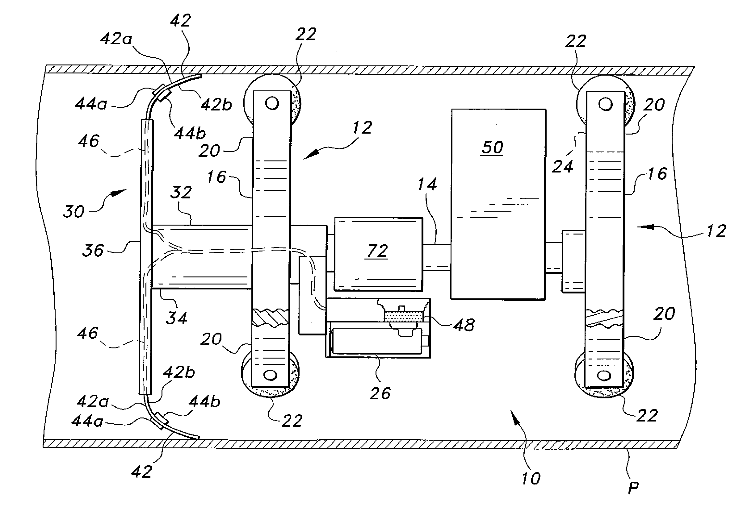
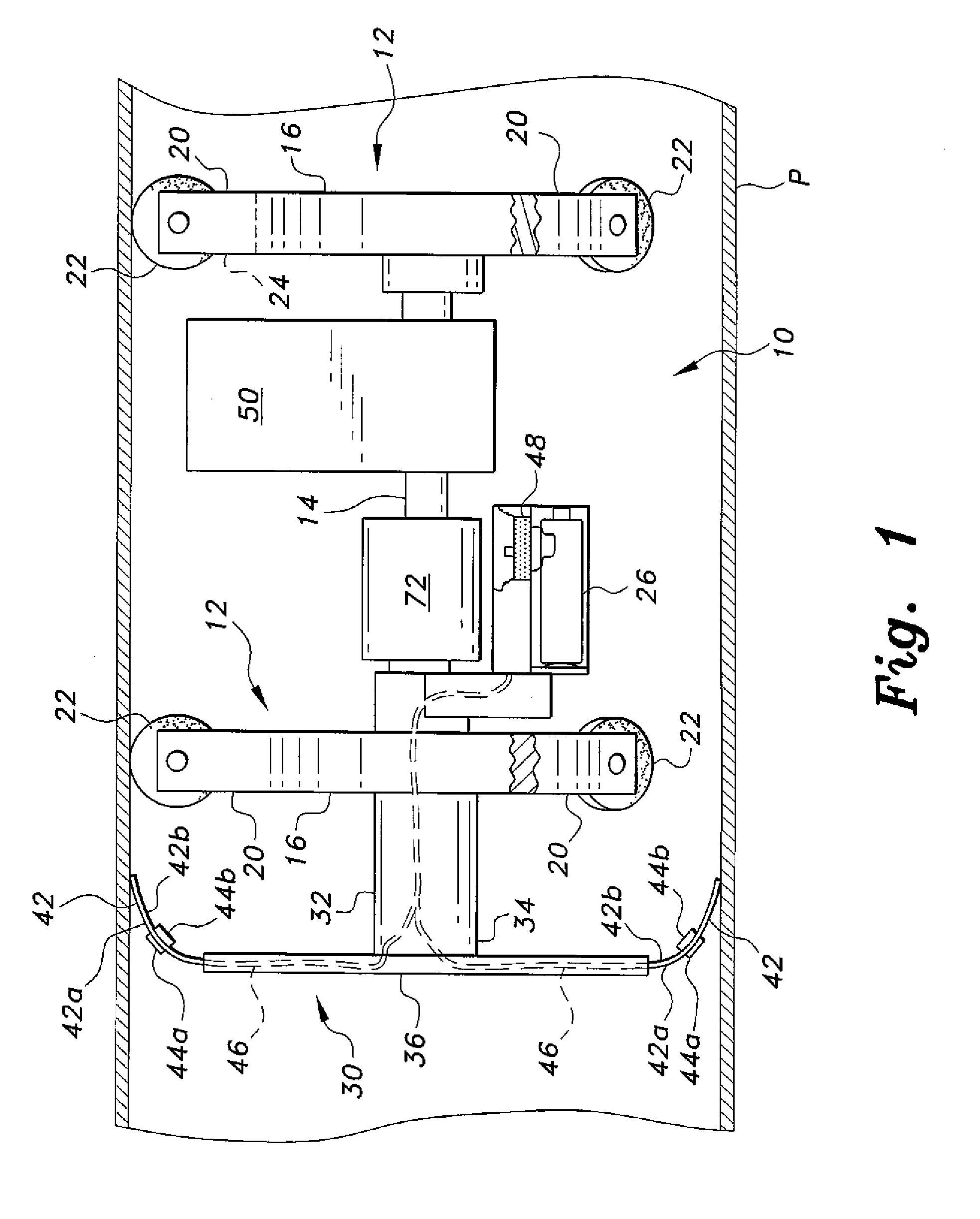
[0019]The pipeline leak detection and repair device is a completely autonomous machine that is capable of traveling through a gas, oil, water, or other pipeline to detect small leaks therein. Moreover, the device automatically seals those leaks nearly simultaneously as it passes them. The only delay is the very short time span between the detection of the leak at the front of the device and the sealing of the leak by the mechanism toward the rearward portion of the device as the device travels through the pipeline.

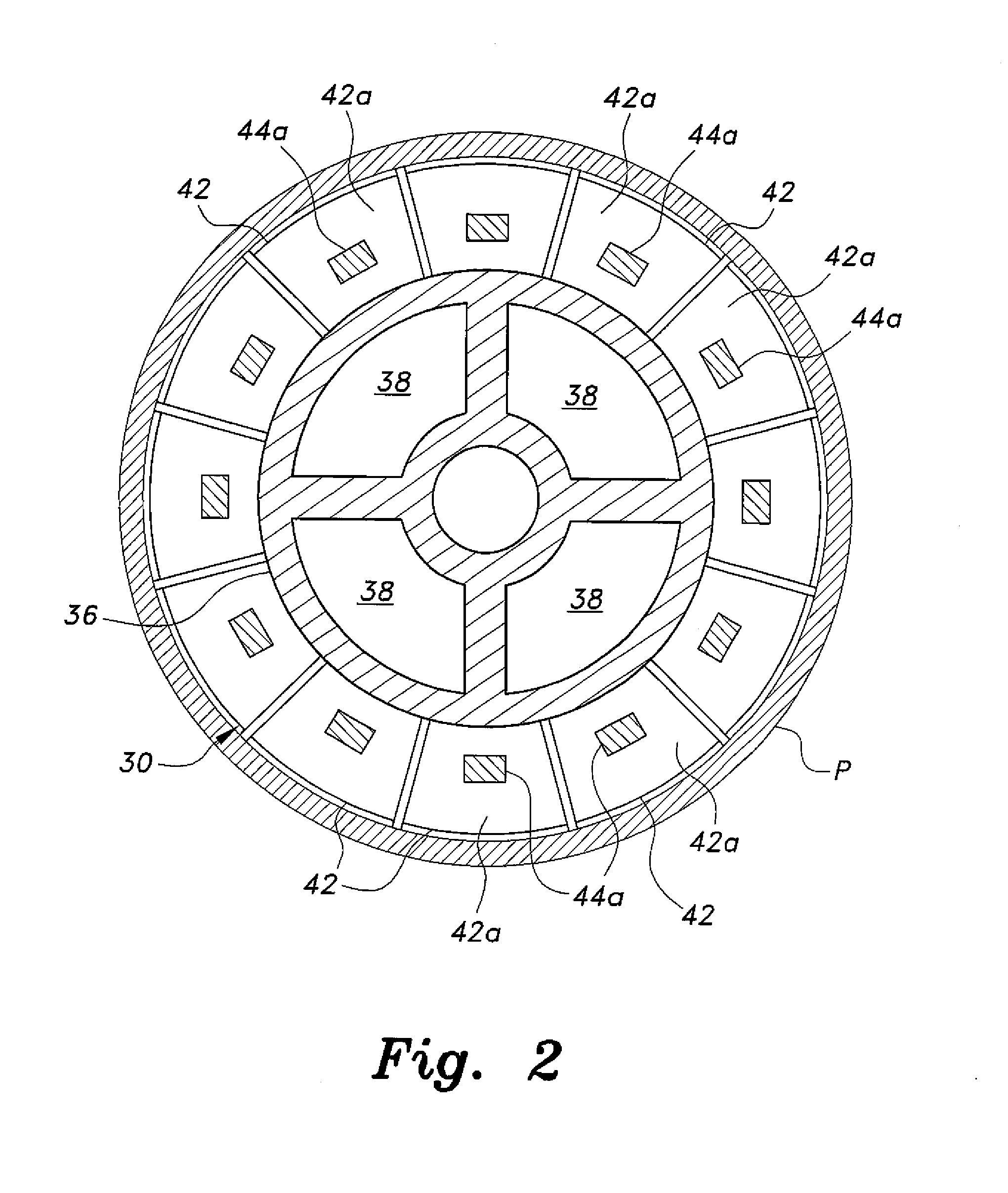
[0020]FIG. 1 of the drawings provides a schematic side elevation view of the pipeline leak detection and repair device 10, shown traveling through a pipeline P. The device 10 comprises substantially identical front and rear supports 12 joined by an axial connecting column 14. The only difference between the two supports is their relative locations and the installation of a drive motor to drive at least one of the wheels on one of the supports, as discussed further below.

[0...


PUM


Abstract

The pipeline leak detection and repair device is an autonomous machine that travels through a pipeline to detect very small leaks therein. The device also repairs those leaks with an on-board repair component. The repair occurs nearly simultaneously with the leak detection as the device passes the leak. The device includes a plurality of thin, flexible sensor leaves in a radial array. The leaves are positioned to place them nearly in contact with the inner surface of the pipe wall. Each leaf includes two sensors installed on its opposite surfaces. Flexure of the leaf due to changes in pressure gradient as the leaf passes a leak results in signals from the sensors being sent to an onboard processor. The processor determines the position of the affected leaf, and rotates a repair component to apply a pressure-sensitive tape patch over the leak as the repair component passes the leak.

Description

BACKGROUND OF THE INVENTION[0001]1. Field of the Invention[0002]The present invention relates generally to autonomous robotic mechanisms, and particularly to a pipeline leak detection and repair device. The device travels through a fluid pipeline (e.g., water, gas, oil, etc.), detects small leaks, and repairs those leaks automatically.[0003]2. Description of the Related Art[0004]Fluid leakage from pipelines, e.g., gas, oil, and water, is a chronic problem in the industry. The financial losses resulting from fluid loss can be significant, depending upon the value of the fluid and the size of the leak, among other factors. Moreover, many pipeline leaks occur in low pressure lines, with contamination leaking into the pipe rather than outward from the pipe. This is a major concern in the case of potable water, as even a very small leak can contaminate a water supply with bacteria or other hazards. In other cases, the fluid carried in the pipeline may be hazardous to the environment (e.g...

Claims


Application Information

Patent Timeline
Patent Type & Authority Applications(United States)
IPC IPC(8): F16L55/18
CPCF16L55/18F16L55/1645F16L55/32
Inventor KHALIFA, ATIA ESMAEILMEKID, SAMIR
Owner KING FAHD UNIVERSITY OF PETROLEUM AND MINERALS
Why Eureka
Try Eureka