
Groundwater organic pollutant restoration device and method

A technology for organic pollutants and groundwater, applied in the fields of adsorbed water/sewage treatment, reduced water/sewage treatment, oxidized water/sewage treatment, etc., can solve the problems of high maintenance cost, difficult operation, long repair cycle, etc., and achieve easy management. Maintenance, operability, and the effect of reducing repair costs

Active Publication Date: 2014-02-26
北京德瑞科森环保科技有限公司
View PDF6 Cites 21 Cited by
  • Summary
  • Abstract
  • Description
  • Claims
  • Application Information

AI Technical Summary

Problems solved by technology

However, it faces problems such as long repair period, difficult operation and high maintenance cost, and is affected by various environmental factors such as the types of pollutants in the polluted aquifer, the complexity of the medium structure of the soil and aquifer, and geochemistry in practical engineering applications. , it is difficult to achieve the original goal of its technical design

Method used


Image

  • Groundwater organic pollutant restoration device and method
  • Groundwater organic pollutant restoration device and method

Examples


Embodiment 1

[0049] For the shallow groundwater polluted by nitrobenzene, the buried depth is 3.5m, the thickness of the aquifer is 3-4.5m, and the permeability coefficient is 4.5m / d through micro-water test.

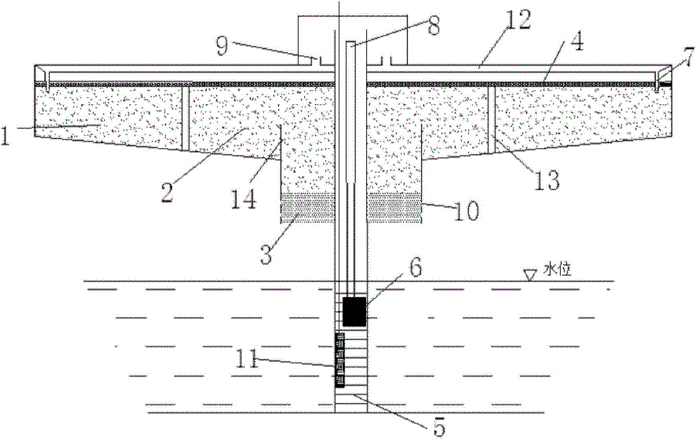
[0050]To construct a groundwater pumping well, the depth of the screen pipe 5 is 4.5m, and its length is 1.5m. Excavate the outer circle with a radius of 3m and a depth of 1.5m; excavate a circle with a radius of 1m at the bottom of the circular pit with a depth of 0.5m. The bottom of the round pit is filled with 30cm of fine sand (particle size 1.6mm-2.2mm) as a fast seepage area, and part of the fine sand is filled with 20cm of small particle size zeolite (particle size 5mm-7mm) and persulfate slow-release material (particle size 6mm ), on this basis, the area with a radius of 1.5m and a height of 1.3m is filled with small particle size zeolite (particle size 5mm-7mm) and persulfate slow-release material (particle size 6mm), and the remaining annular area is filled Reducing mediu...

Embodiment 2

[0052] Choose an abandoned gas station polluted by vinyl chloride, the groundwater depth is about 9m, the aquifer thickness is nearly 6m, and its permeability coefficient is 5.1 / d.

[0053] To build a groundwater pumping well, the depth of the screen pipe is 11m and the length is 3m. Excavate a circular pit with a radius of 4m and a depth of 2m; excavate a circle with a radius of 1.5m and a depth of 4m at the bottom of the circular pit. Anti-seepage is adopted on the sides of the entire pit, and the bottom of the pit is filled with fine sand (particle size 2.0mm-2.8mm) with a height of 3.2m as the fast seepage area, and the upper part of the fast seepage area is filled with 80cm small particle size zeolite (particle size 7mm-9mm) and persulfate slow-release material (particle size 8mm), and then fill the circular area with a radius of 2.5m above the bottom circular pit with small particle size zeolite (particle size 5mm-7mm) and persulfate slow-release material (particle size...


PUM

PropertyMeasurementUnit
Permeability coefficientaaaaaaaaaa
Particle sizeaaaaaaaaaa

Abstract

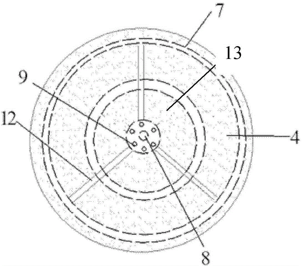
The invention relates to a groundwater organic pollutant restoration device, which includes: a pumping system, a water distribution system, a reducing medium filling area, an annular hydraulic load buffer area, an adsorption-advanced oxidation medium filling area, a rapid seepage area and an online monitoring system. According to the invention, water is pumped by the pumping system, water is uniformly distributed by the water distribution system, reduction reaction and oxidation reaction are realized step by step in the reducing medium filling area and the adsorption-advanced oxidation medium filling area so as to realize the purpose of removing organic pollutants from groundwater, and the restored groundwater can rapidly seep into an underground aquifer. Thus, redox reaction can be performed in stages, groundwater organic matters can be efficiently removed, and the disposal problem of the restored groundwater can be effectively solved. The invention also relates to a method for restoration of groundwater organic pollutants by the restoration device.

Description

technical field [0001] The invention belongs to the technical category of groundwater pollution restoration, and in particular relates to a groundwater organic pollutant restoration device. [0002] The invention relates to a method for repairing organic pollutants in groundwater by using the repair device. Background technique [0003] The remediation technology of organic pollutants in groundwater has become a hot issue in the prevention and control of groundwater pollution in the world. [0004] At present, there are many technologies researched at home and abroad, including extraction treatment, in-situ aeration, permeable reaction wall, in-situ chemical oxidation, in-situ bioremediation, etc. At the same time, there have been some effective groundwater organic pollution remediation projects, including pumping out treatment, in-situ aeration, PRB and other remediation cases, but these remediation technologies have their own advantages and disadvantages in actual enginee...

Claims


Application Information

Patent Timeline
IPC IPC(8): C02F1/70C02F1/72C02F1/28
Inventor 席北斗姜永海安达杨昱李鸣晓张进保马志飞
Owner 北京德瑞科森环保科技有限公司
Learn More