High-frequency isolated type boost three-level inverter

A three-level inverter and high-frequency isolation technology, which is applied in the direction of electrical components, AC power input conversion to DC power output, output power conversion devices, etc., can solve the problem of large input current ripple and low power factor on the input side , small output capacity, etc., to ensure the quality of the output waveform, reduce the number of power conversion stages, and solve the problem of whereabouts

Inactive Publication Date: 2014-08-13
NANJING UNIV OF SCI & TECH
View PDF3 Cites 5 Cited by
  • Summary
  • Abstract
  • Description
  • Claims
  • Application Information

AI Technical Summary

Problems solved by technology

However, the diode-clamped and capacitor-clamped multi-level multi-point flat inverter technologies have defects such as single topology and no electrical isolation: the cascaded multi-level inverter technology with independent DC power supply has complicated circuit topology on the input side Low power factor, low conversion efficiency, low power density and other defects
[0005] So far, people have made remarkable achievements in the research of buck and buck-boost high-frequency link DC-AC converters, but buck and buck-boost high-frequency link DC-AC converters have large input current ripples, Defects such as low reliability (buck type) and small output capacity (buck-boost) when the load is short-circuited
The research on Boost converters mainly focuses on Boost DC-DC, AC-AC, and AC-DC converters, including non-electrical isolation and electrical isolation. The research on Boost three-level converters mainly focuses on There is no isolation transformer type, but there is little research on Boost three-level converters with isolation transformers, especially Boost three-level inverters with isolation transformers

Method used


Image

  • High-frequency isolated type boost three-level inverter

Examples


Embodiment Construction

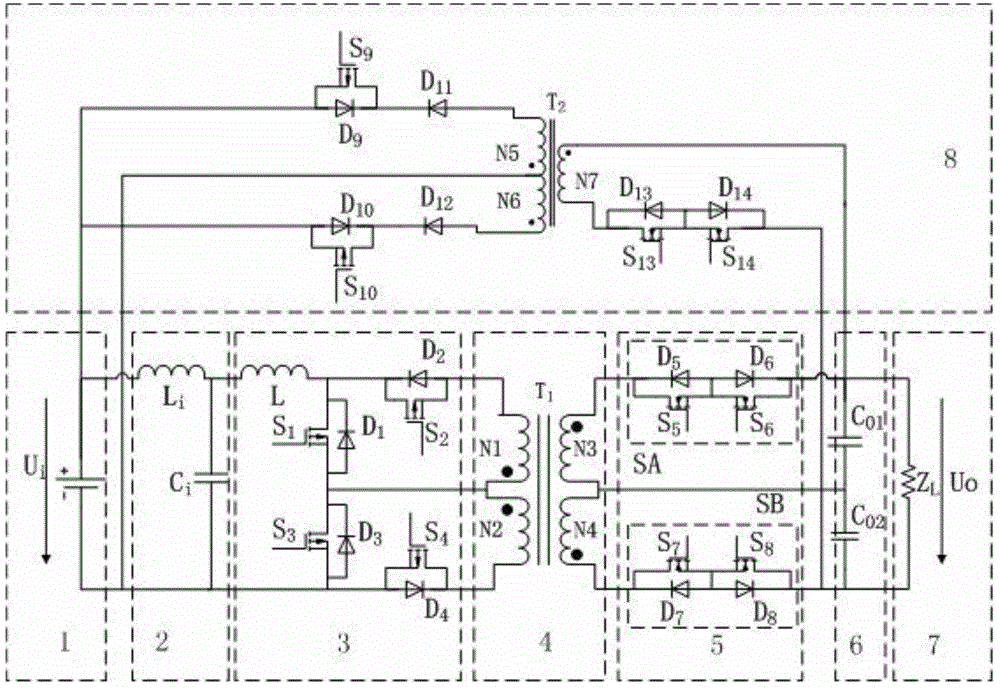
[0024] In order to better understand the technical content of the present invention, specific embodiments are given together with the attached drawings for description as follows.

[0025] Such as figure 1As shown, according to the preferred embodiment of the present invention, the high-frequency isolated step-up three-level inverter consists of an input DC power supply unit 1, an input filter 2, a high-frequency inverter 3, and a high-frequency inverter connected in sequence. A transformer 4, a cycloconverter 5, an output voltage dividing capacitor 6, an output AC load 7, and a high-frequency electrical isolation flyback converter 8 are formed. The input DC power supply unit 1 is connected to one end of the input filter 2, and the input filter 2 The other end is connected with one end of the high-frequency inverter 3, the other end of the high-frequency inverter 3 is connected with the primary winding of the high-frequency transformer 4, and the secondary winding of the high-...


PUM


Abstract

The invention provides a high-frequency isolated type boost three-level inverting circuit which is composed of a Boost inverting circuit and a flyback type energy feedback circuit. The Boost inverting circuit is composed of an input direct-current power supply unit, an input filter, a high-frequency inverter, a high-frequency transformer, a frequency converter, an output filtering capacitor and an output alternating-current load which are sequentially connected. A Boost converter can only increase the voltage and can not decrease the voltage, so that the output voltage can not be decreased, and the voltage can not meet the requirement for the output sine waveform. In order to ensure the quality of the output sine waveform in the period and solve the problem of the orientation of reactive energy of the output filtering capacitor and the load, the high-frequency electrical isolation flyback type converter energy feedback circuit is added between the output load and an input power supply. The inverter has the advantages that the number of power conversion stages is small, the number of power switching devices is small, input ripple waves are small, the voltage stress of a power switching tube is low, the dual-directional power stream and high-frequency electrical isolation are achieved, and the spectrum characteristic of the voltage at the front end of the output filter is good.

Description

technical field [0001] The invention belongs to the technical field of power electronic conversion, in particular to a novel high-frequency isolated boost-type three-level inverter. Background technique [0002] At present, the research of power electronics researchers at home and abroad mainly focuses on two-level DC-AC converters such as non-electrically isolated, low-frequency and high-frequency electrically isolated; for the research on multi-level converters, Mainly focus on multi-level DC-DC, AC-AC and DC-AC-DC converters, while the research on multi-level DC-AC converters is very little, and only limited to non-isolated, low frequency or intermediate frequency isolation DC-AC multi-level DC-AC converter, but research on high-frequency isolated multi-level two-stage power conversion inverter is less. [0003] There are three main types of topologies for multilevel inverters: (1) diode-clamped inverters, (2) capacitor-clamped inverters, and (3) cascaded inverters with ...

Claims


Application Information

Patent Timeline
Patent Type & Authority Applications(China)
IPC IPC(8): H02M7/537H02M1/14
Inventor 胥佳梅李磊项泽宇柳成潘敏
Owner NANJING UNIV OF SCI & TECH
Why Eureka
Try Eureka