Ambient air temperature and/or humidity sensor

a sensor and ambient temperature technology, applied in the field of sensors, can solve the problems of high sensor visible, not always desirable, and inability to maintain accuracy in the presence of strong sunlight, and achieve the effect of accurate recording of ambient temperatur

Inactive Publication Date: 2002-06-18
SELEX ES
View PDF13 Cites 11 Cited by
  • Summary
  • Abstract
  • Description
  • Claims
  • Application Information

AI Technical Summary

Problems solved by technology

One of the problems with sensors used to sense temperature and / or humidity is that of maintaining accuracy in the presence of strong sunlight.
However, white makes the sensor highly visible which is not always desirable.
With no significant air movement on a sunny day, the temperature of the interior of the housing can rise giving an inaccurate record of ambient temperature.
Whilst it has been proposed to utilise a powered fan to provide a flow of air over a sensing device to reduce that problem, the use of a fan is undesirable in dust and sand environments and can become noisy and unreliable.
Although the downward flow of air between the tube and shielding member will help to insulate the sensing device from solar radiation where the sensing device is arranged on the tube, it is desirable to produce the shielding member from an insulative material such as plastics so that the shielding member does not readily heat up and radiate heat across the clearance space to the sensing device.

Method used


Image

  • Ambient air temperature and/or humidity sensor
  • Ambient air temperature and/or humidity sensor

Examples


Embodiment Construction

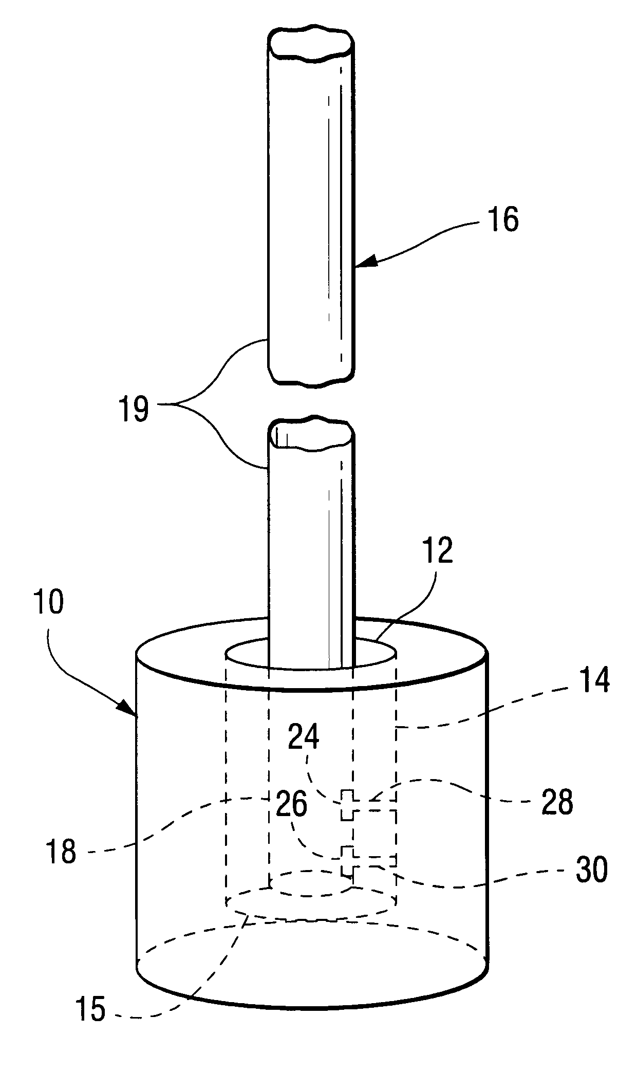
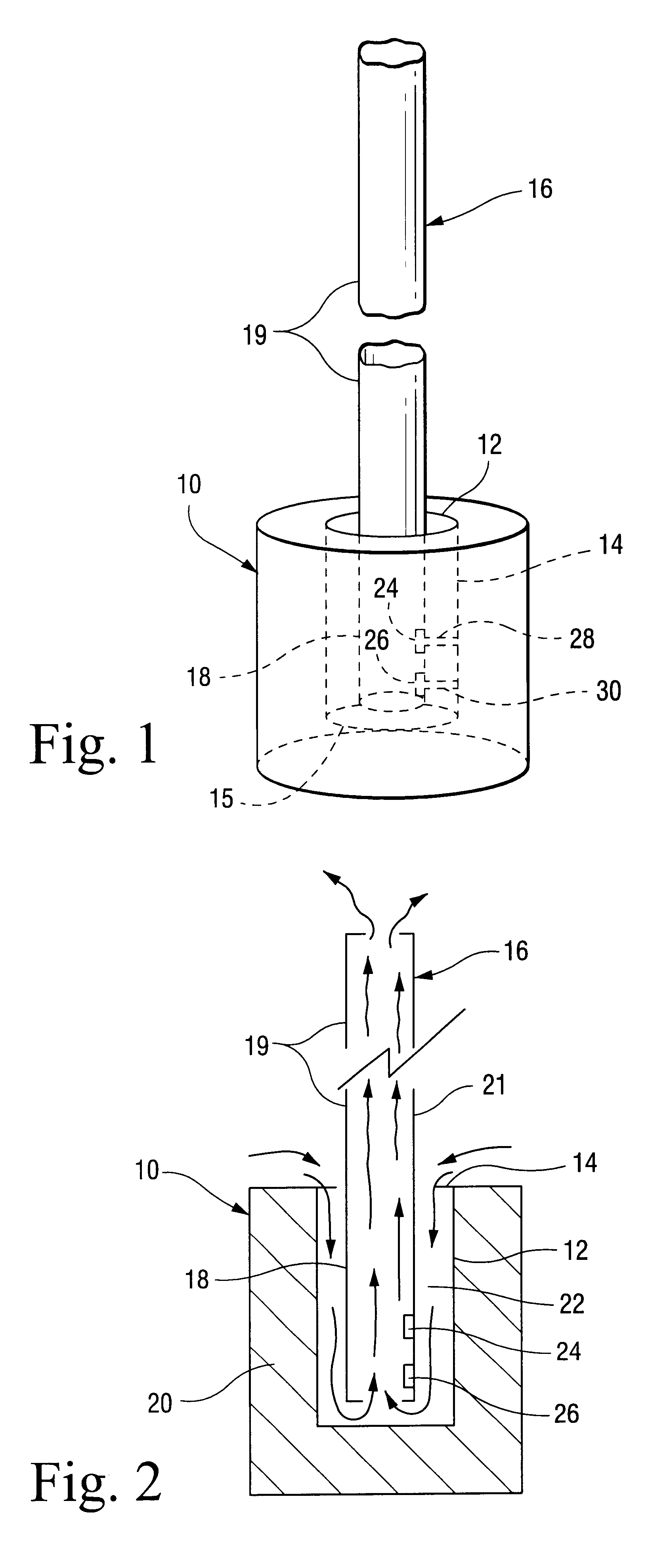
The sensor comprises a pot-like outer member 10 made of heat insulative material such as a plastic. The outer member 10 has therein a vertical hole 12 which has an opening 14 at its upper end and a closed lower end 15 as viewed in the drawings. An elongate inner member in the form of a thin-walled tube 16 is provided which has a lower portion 18 positioned in the hole 12 and an upper portion 19 which projects out of the opening 14 and extends above the outer member 10.

The bottom of the lower portion 18 is spaced from the closed lower end 15 of the hole 12. As will be appreciated from the drawings, the outer member 10 has a wall 20 which is considerably thicker than the wall of the tube 16, the tube wall being indicated at 21. At least the upper portion 19 of the tube 16 is metallic, e.g. made of aluminium. The hole 12 and the tube 16 are of circular transverse cross-section and are substantially coaxial so as to define an annular clearance space 22 between them.

The lower portion 18 ...


PUM

PropertyMeasurementUnit
conductiveaaaaaaaaaa
metallicaaaaaaaaaa
temperatureaaaaaaaaaa

Abstract

The sensor has an outer member 10 formed with an upwardly directed hole 12 having an open upper end 14. An inner member in the form of a tube 16 is provided having a lower portion 18 positioned in the hole 12 and an upper portion 19 which projects above the outer member 10. Solar radiation applied to the upper portion 19 of the tube 16 creates a chimney effect which causes air to flow upwardly inside the tube 16 and downwardly from the open upper end 14 through a space 22 between the inner and outer members 10, 16. Sensing devices 24, 26 for sensing temperature and humidity are arranged within the outer member 10 and in the air flow path.

Description

1. Field of the InventionThe invention relates to a sensor and is primarily concerned with a sensor for sensing temperature and / or humidity of ambient air.2. Discussion of Prior ArtOne of the problems with sensors used to sense temperature and / or humidity is that of maintaining accuracy in the presence of strong sunlight. It is known to install sensing devices in ventilated housings such as a Stevenson Screen which are coloured white to minimise the effect of sunlight. However, white makes the sensor highly visible which is not always desirable.When measuring temperature and / or humidity, a flow of air over the sensing device should ideally be provided. In the Stevenson Screen, air flows through the ventilated housing but relies on a slight wind to achieve that. With no significant air movement on a sunny day, the temperature of the interior of the housing can rise giving an inaccurate record of ambient temperature. Whilst it has been proposed to utilise a powered fan to provide a fl...

Claims


Application Information

Patent Timeline
Patent Type & Authority Patents(United States)
IPC IPC(8): G01W1/17G01N25/56G01W1/00G01K1/20G01K13/02G01W1/04
CPCG01W1/17G01N25/56
Inventor WALKER, JEFFERY C.DEEDMAN, DAVID K.FLEMING, NIGEL P.OUGHTON, BRIAN W.SANDOE, IAIN D.WILTON, PAUL M.
Owner SELEX ES
Why Eureka
Try Eureka