Humidifier with parallel gas flow paths

a gas flow path and humidifier technology, applied in the field of humidification systems, can solve the problems of introducing weight, heat and complexity near the patient, reducing the efficiency of humidification, so as to minimise the condensation rate of vapour and reduce the rate of heat energy loss

Inactive Publication Date: 2006-12-12
FISHER & PAYKEL HEALTHCARE LTD
View PDF95 Cites 116 Cited by
  • Summary
  • Abstract
  • Description
  • Claims
  • Application Information

AI Technical Summary

Benefits of technology

[0016]It is therefore an object of the present invention to provide a humidification system which goes some way to overcoming the above mentioned disadvantages, or which will at least provide the public with a useful choice.
[0034]Wherein said valve comprising an electromechanical actuator connected to a valve member wherein the energisation of said electromechanical actuator varies the position of said valve member thereby varying the restriction provided by said valve means on the flow rate of the portion of said gas in said bypass conduit.
[0037]Wherein a humidification apparatus further comprises a conduit to convey said gas from said outlet to a patient including insulation adapted to minimise the rate of heat energy lost by said gas in said conduit, said controller adapted to energise said humidifier and said air heater to minimise the condensation of the vapour from said gas in said conduit while providing predetermined levels of absolute humidity.

Problems solved by technology

While it discloses a humidity sensor at the patient airway, it doesn't describe the actual humidification configuration to be used.
These have the disadvantage of introducing weight, heat and complexity near the patient which is inconvenient and could be painful to the patient.
There are several disadvantages of the prior art systems using a humidification chamber located remotely from the patient.
However there is no guarantee that the gases leaving such humidifiers are in fact saturated with water vapour.
Another drawback of the prior art systems is that condensation can occur in the (sometimes heated) conduits connecting the patient to the respiratory assistance equipment.
A third disadvantage of such prior art systems is where the gas leaving the humidifier is at 100% relative humidity it must be heated immediately by some form of conduit heater or it may lose heat through the walls of the conduit, which results in condensation and therefore a drop in the amount of absolute humidity contained in the gas.
Another fourth disadvantage of the prior art systems is the need for a sensor very near to the patient, which adds to the weight and bulk of equipment at the patient's airway.
A fifth disadvantage of the prior art systems is that intermittent or varying flow rates will cause the absolute humidity that is generated by the humidifier to be uneven.
Consequently it is difficult for a conduit in such prior art systems to transport these high humidity boluses without condensation and consequent loss of absolute humidity.

Method used


Image

  • Humidifier with parallel gas flow paths
  • Humidifier with parallel gas flow paths
  • Humidifier with parallel gas flow paths

Examples


Embodiment Construction

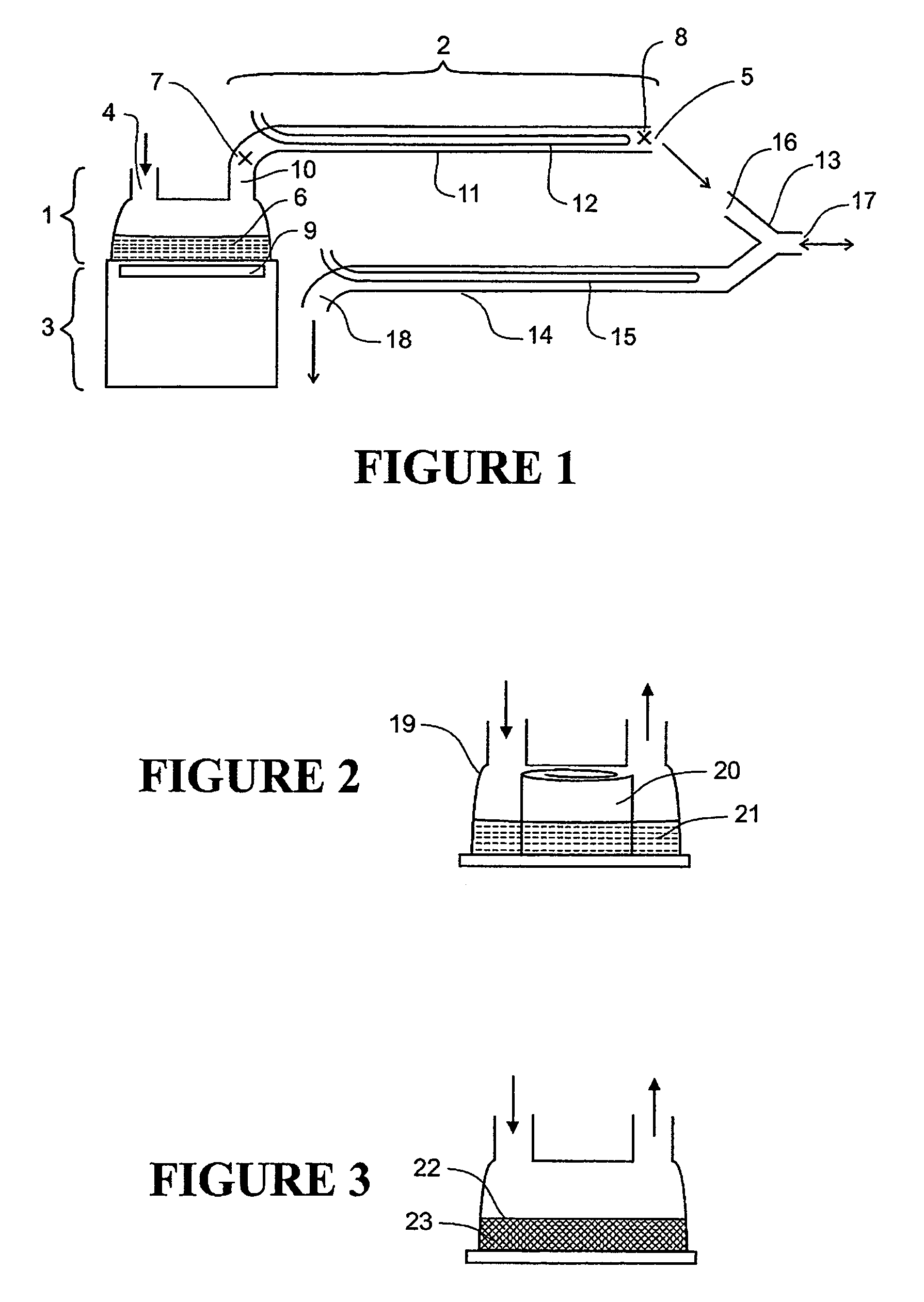
[0061]FIG. 1 illustrates a typical respiratory humidification system, comprised of three parts:[0062]1) a humidification chamber located at a distance from the patient, which heats and substantially saturates gases flowing through it;[0063]2) a delivery system consisting of a flexible tube which carries humidified gases from the humidification chamber 1 to the gas outlet 5; and[0064]3) a heater base which heats the humidification chamber 1 and provides measurement and control functions.

[0065]The gas to be humidified flows into the chamber 1 from port 4 and leaves the delivery system 2 at gas exit port 5. Gas from exit port 5 flows to a patient via a face mask or similar (not shown). The system is controlled using sensors located at positions 7 and 8—typically temperature probes. Dry gases at the gas input 4 are heated and humidified by passing over the surface of hot water 6 in the chamber 1 so that they are substantially saturated with water vapour when they leave chamber 1 at exit...


PUM


Abstract

A humidifier and humidity sensor is disclosed for use with a breathing assistance apparatus. The humidity sensor preferably includes means to sense absolute humidity, relative humidity and / or temperature at both the patient end and humidifier end. The humidifier may also include provision to both control independently the humidity and temperature of the gases. Further, a chamber manifold is disclosed to facilitate easy connection of the humidifier to various outlets, inlets and sensors. A heated conduit is described which provides a more effective temperature profile along its length.

Description

[0001]This application is a divisional application of U.S. patent application Ser. No. 09 / 808,567 filed on Mar. 14, 2001, entitled “Breathing Assistance Apparatus”, now U.S. Pat. No. 6,918,389.BACKGROUND TO THE INVENTION[0002]1. Field of the Invention[0003]The present invention relates to the use of an humidification system particularly, but not solely, for providing respiratory assistance to patients receiving mechanical ventilation or respiratory support.[0004]2. Summary of the Prior Art[0005]A number of methods are known in the art for supplying humidified gases to a patient requiring breathing assistance. Such prior art humidifiers generally comprise a source of pressurised air (or other mixture of gases), a humidification chamber including a source of water and a heating means to vaporise the water, and a conduit to convey the humidified gases to the patient or user.[0006]For example U.S. Pat. No. 4,038,980 describes a “flash vaporisation” humidifier where water drips onto a lo...

Claims


Application Information

Patent Timeline
Patent Type & Authority Patents(United States)
IPC IPC(8): A61M15/00A62B7/00A61M16/08A61M16/10A61M16/16
CPCA61M16/08A61M16/1075A61M16/16A61M16/162A61M16/109A61M16/1095A61M16/161A61M16/142A61M16/024A61M2205/3368A61M2016/102A61M16/1085A61M16/0003A61M16/0883A61M2016/003A61M2205/50A61M16/0875A61M16/10
Inventor SEAKINS, PAUL JOHNSMITH, MALCOLM DAVIDTHUDOR, MOHAMMAD
Owner FISHER & PAYKEL HEALTHCARE LTD
Why Eureka
Try Eureka