Tape cartridge

a tape cartridge and single-reel technology, applied in the field of single-reel tape cartridges, can solve the problems of failure to release the brake and further assembling work impossible,

Inactive Publication Date: 2002-06-25
TDK CORPARATION
View PDF13 Cites 30 Cited by
  • Summary
  • Abstract
  • Description
  • Claims
  • Application Information

AI Technical Summary

Problems solved by technology

In that case the brake release plate would be deflected along its periphery because the latter is pushed upward while the center of the plate remains in contact with the brake button, leading to failure in positive release of the brake.
At the time of

Method used


Image

  • Tape cartridge
  • Tape cartridge
  • Tape cartridge

Examples


Embodiment Construction

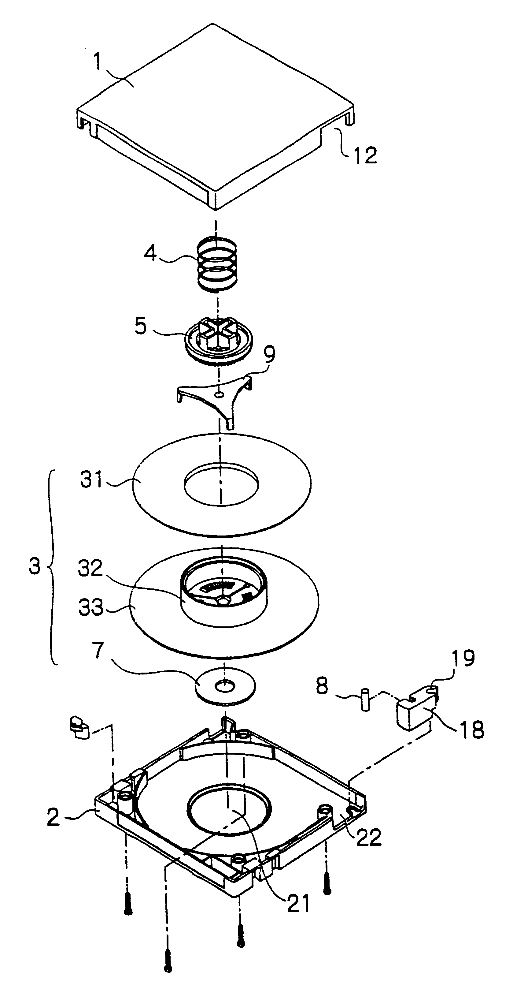
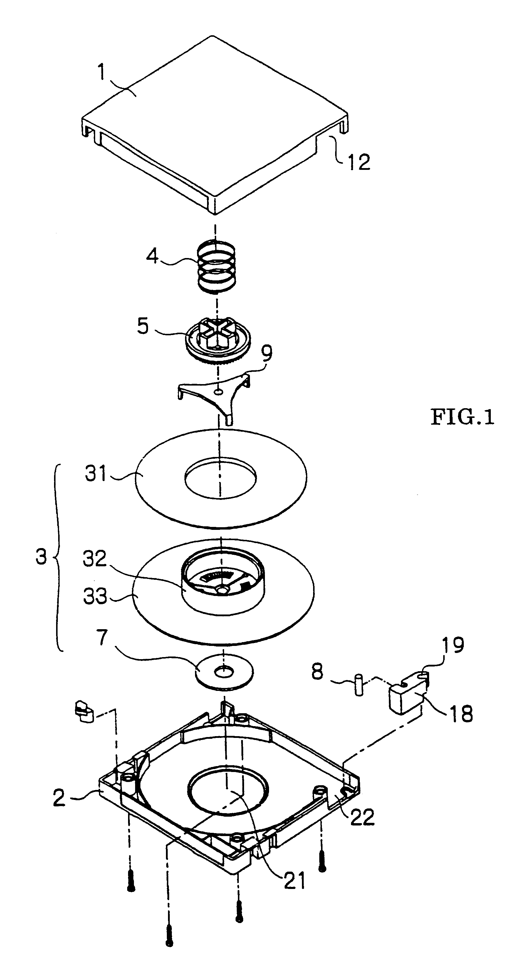
FIG. 1 is an exploded view of a tape cartridge embodying the present invention.

The cartridge comprises a housing consisting of upper and lower casings 1, 2 and a single tape reel 3 on which a length of tape is wound and which is turnably contained in the housing.

Lower casing 2 has an opening 21 through which a drive shaft of a recorder is inserted into the housing. Upper and lower casings 1, 2 have cutouts 12, 22, respectively, which are joined to form an opening through which tape is to be pulled out.

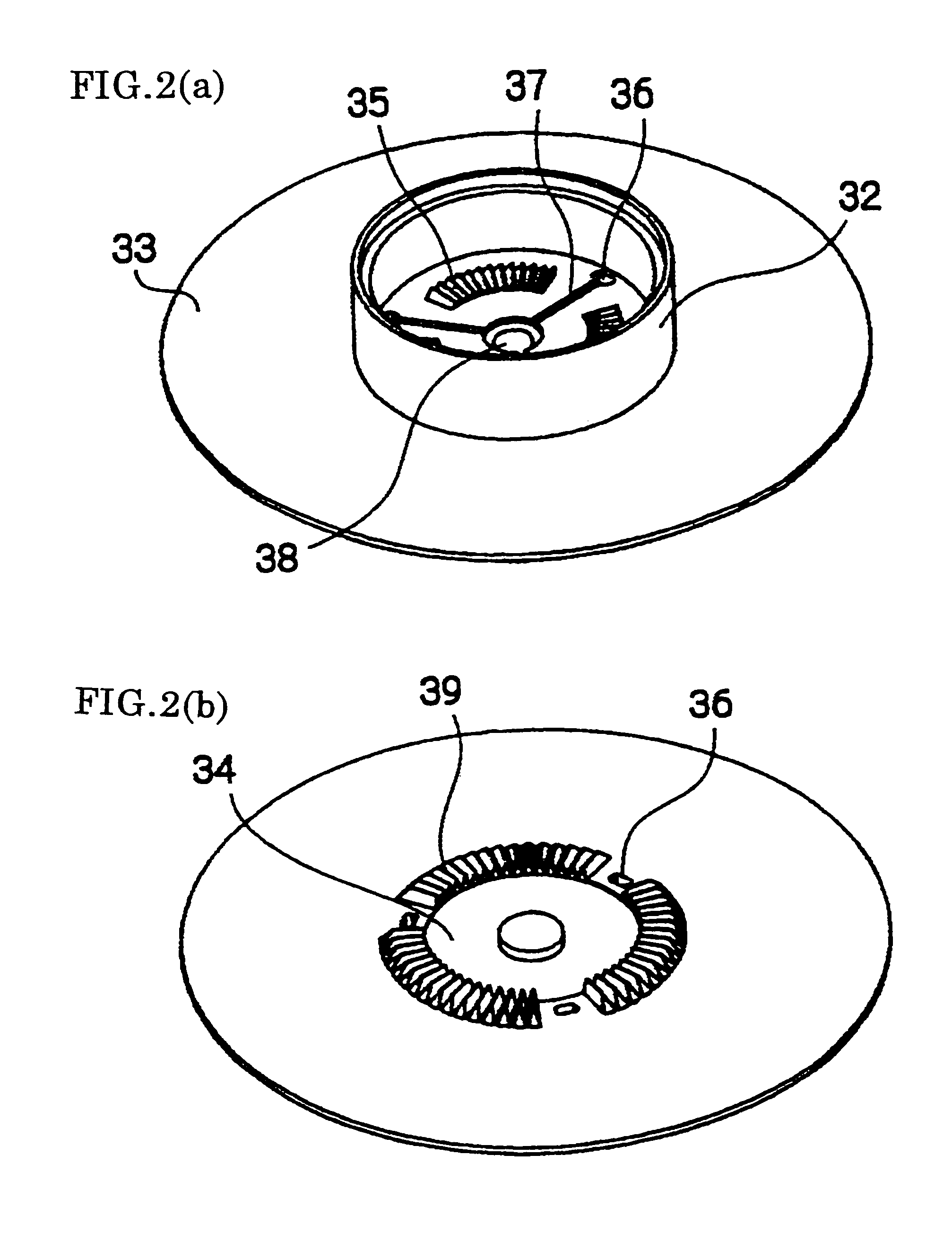
Tape reel 3 consists of an upper flange 31, a hub 32 formed in one piece with a lower flange 33, and a metal disk 7 that fits integrally to the underside of hub 32. Drive teeth 39 are formed on the underside along the periphery of the metal disk 7 and adapted to engage a drive shaft of a recorder. (The metal disk is magnetically attracted by the drive shaft of the recorder to turn tape reel 3.) There is no member to fix the tape in place, because the tape is directly affixed to the out...


PUM


Abstract

In a tape cartridge which turnably holds within a housing a single tape reel on which a length of tape is wound, the tape reel consisting of an upper flange, a lower flange, and a hub which is open at top and is closed at the bottom, the hub having a metal disk in the center of the outer bottom surface and teeth formed around the outer periphery of the metal disk for engagement with a drive shaft of a recorder, the underside of the hub having throughholes for engagement with a brake release plate, the hub having teeth formed on the inner bottom surface to engage a brake lock, the brake release plate consisting of a main plate disposed between the brake lock and the inner surface of the hub and a plurality of legs adapted to fit in the throughholes in the bottom of the hub, the brake lock having brake teeth formed on the periphery of its underside and a contact area in the center for engagement with the brake release plate, the teeth of the hub and the brake teeth of the brake lock being in mesh to prevent unwanted turning of the tape reel, and further including a spring member provided between the brake lock and an upper casing of the housing to urge the brake lock in the braking position:the invention forms a short toe on the outer end of each leg of the brake release plate so as to prevent the leg from coming off, out of engagement with, a corresponding hole of the hub; provides a reinforcing structure between the center of main plate and the legs of the brake release plate; precludes the possibility of a once-incorporated brake release plate coming off from the hub during the course of assembling; and ensures positive release action of the brake release plate.

Description

1. Field of the InventionThis invention relates to a single-reel type tape cartridge for use with magnetic recording-reproducing apparatus (hereinafter called a "recorder").1. Prior ArtJapanese Patent Application Kokai No. 63-251983 discloses a single-reel type tape cartridge having a brake lock which applies the brake on the tape reel and releases it by upward and downward motion within a hub on which the tape is wound.FIG. 6 is an exploded view of a single-reel type cartridge of the prior art. FIG. 7 is a cross sectional view showing essential parts of the cartridge. For easier reference the components are shown upside down. The cartridge comprises a housing composed of an upper casing 1 and a lower casing 2, and a single tape reel 3 on which a length of tape 14 is wound and which is turnably held within the housing.Upper and lower casings 1, 2 are formed, respectively, with cutouts 12, 22 which are joined to provide an opening into which a leader block 18 is inserted so as to be ...

Claims


Application Information

Patent Timeline
IPC IPC(8): G11B23/107G11B23/04G11B23/08
CPCG11B23/043G11B23/107G11B23/044
Inventor SHIMA, MOTOHIKOKANEDA, HIROSHIOKAMURA, MASATOSHI
Owner TDK CORPARATION
Why Eureka
Try Eureka