Locking cylinder

Inactive Publication Date: 2002-07-02
TALLERES DE ESCORIAZA SA
View PDF9 Cites 27 Cited by
  • Summary
  • Abstract
  • Description
  • Claims
  • Application Information

AI Technical Summary

Problems solved by technology

The application of electronics for operating locking cylinders presents specific problems relating to the autonomy of functioning by means of incorporation of its own electrical supply source, and attaining a reduced size that can be extreme, in order to be able to place everything in the small space where it can reside in the planar vertical extension of a locking cylinder of European profile (in a shape reminiscent of a pear), since this European profile is used most often and in order to conceive the most unfavorable case of the cylinder types most often employed.
Most of the energy consumption is used for activating the rotational-blocking electromechanical device.
These forces are integrally supported by the brace and are transmitted to the micromotor axis in the form of bending moments that produce deformations and permanent clearances, which exercise negat

Method used


Image

  • Locking cylinder
  • Locking cylinder
  • Locking cylinder

Examples


Embodiment Construction

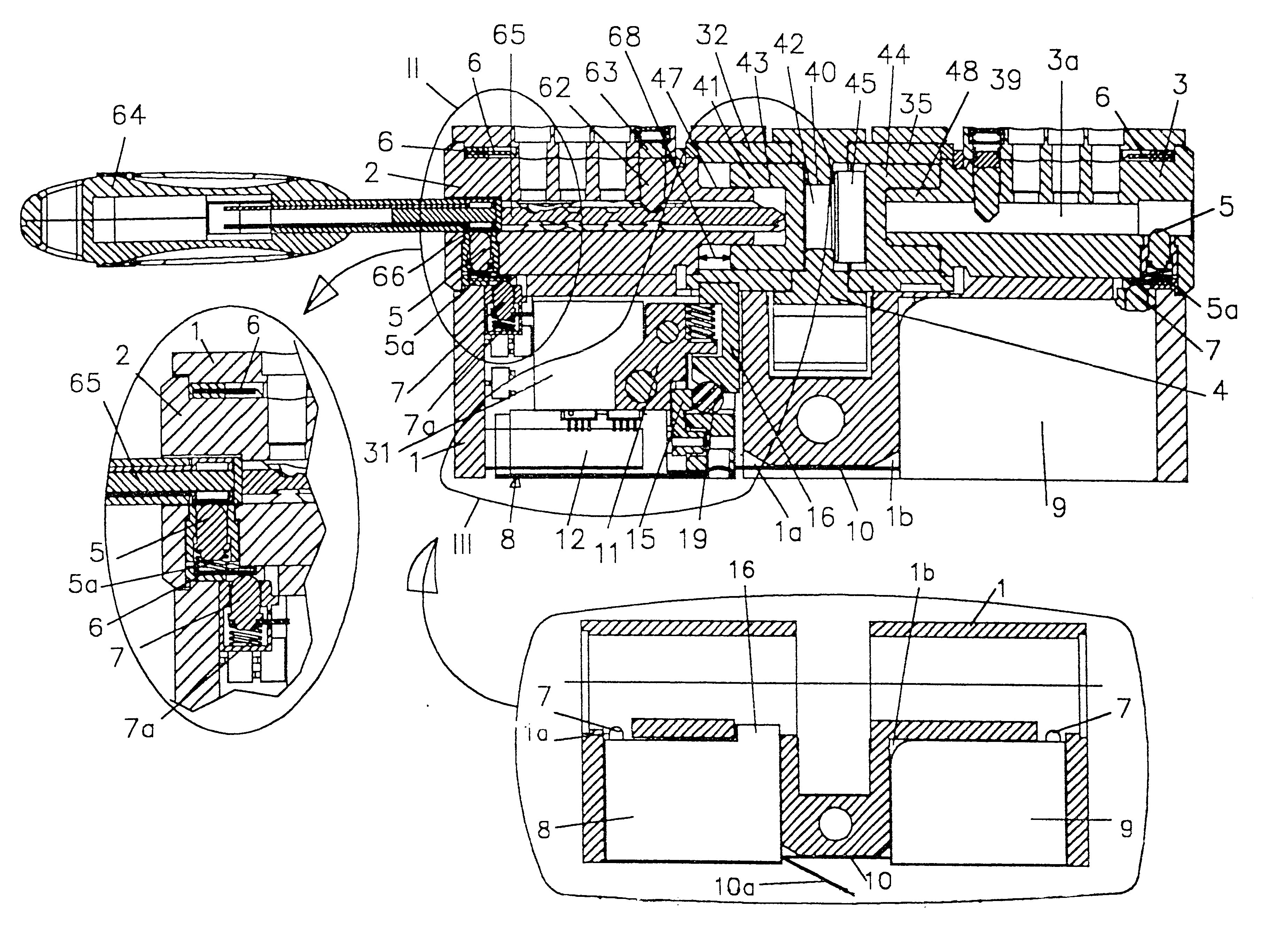
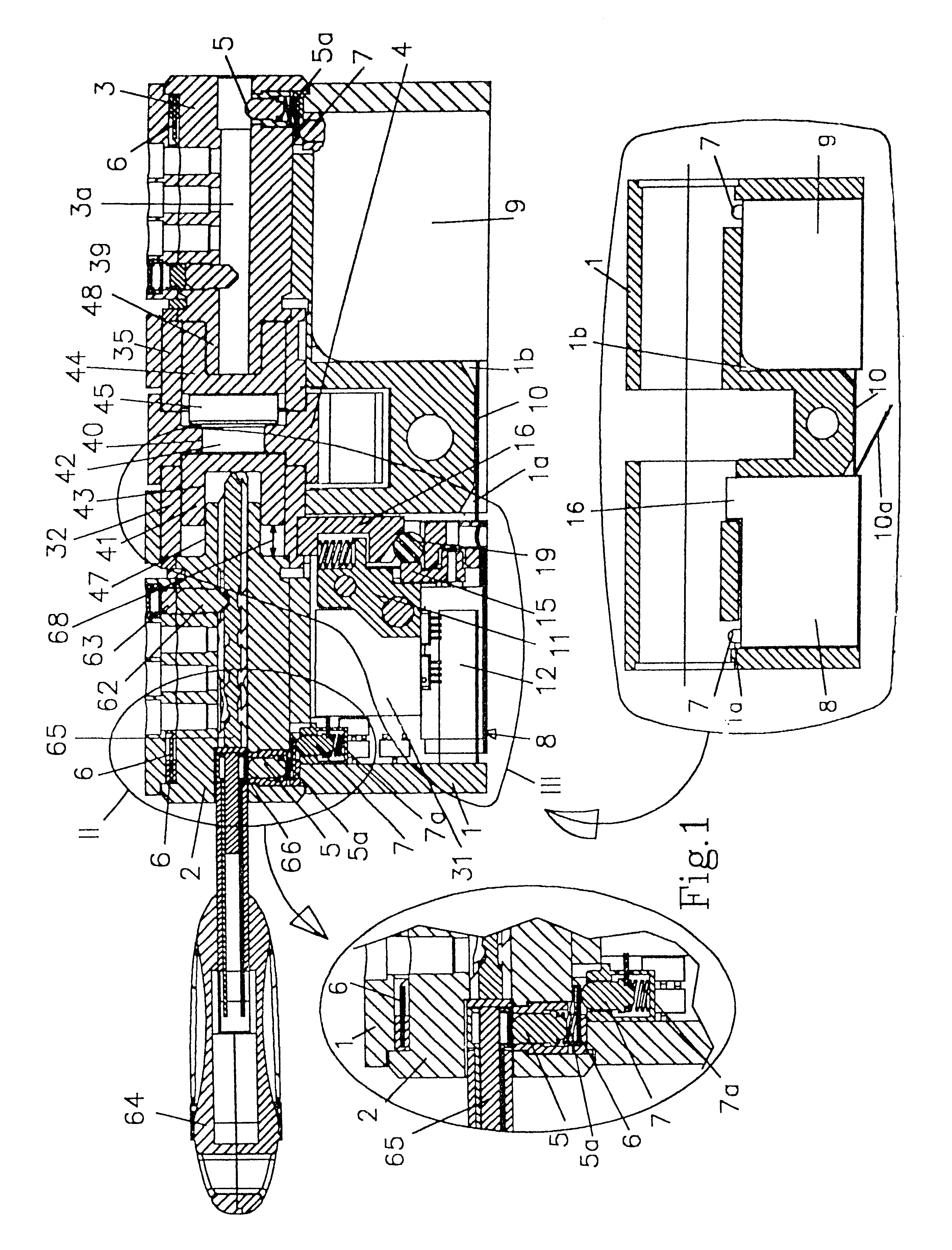
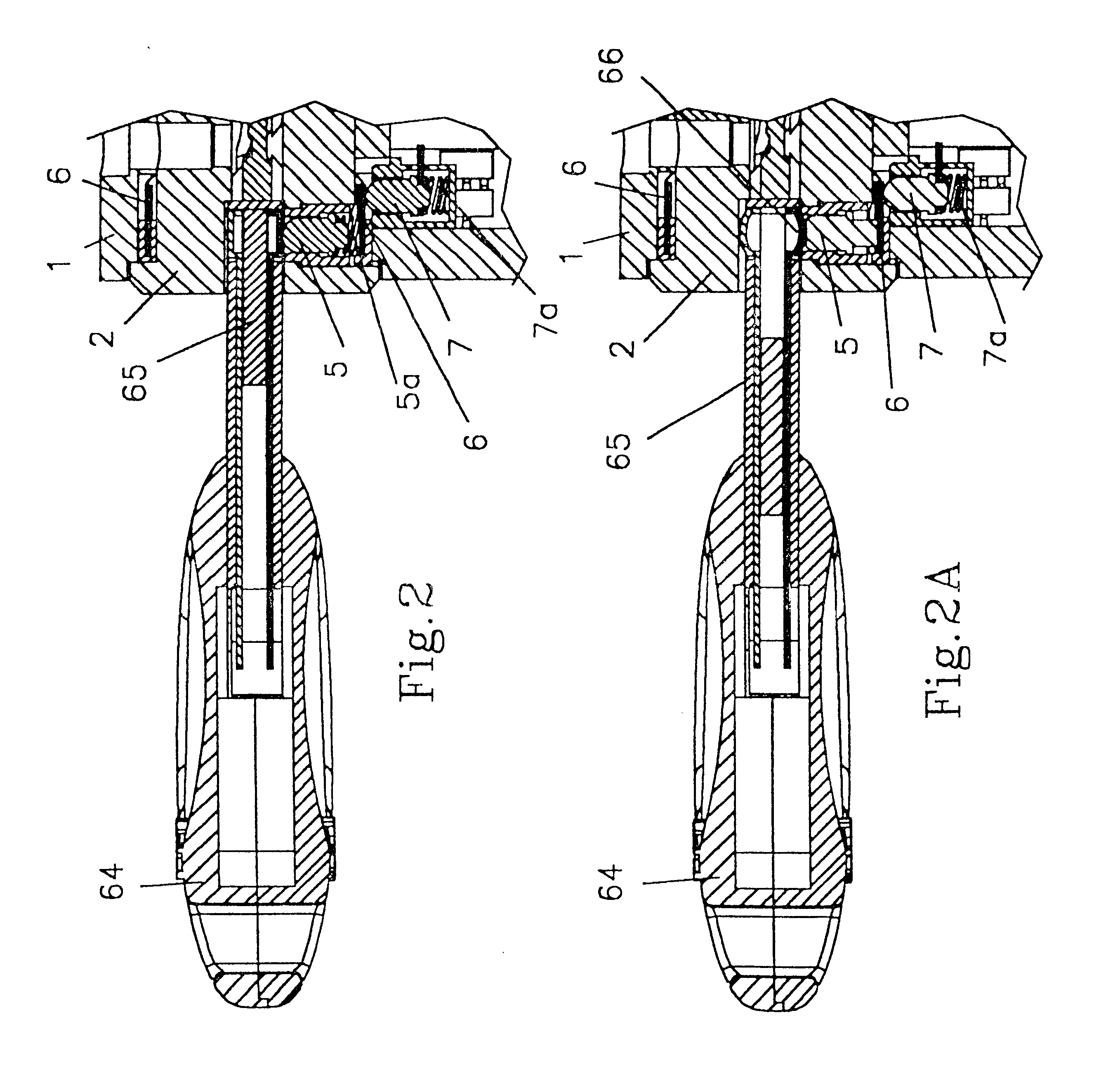
FIG. 1 shows a preferred form of embodiment of the new cylinder to be actuated by means of an electronic key (64) both externally as well as internally of the lock; this electronic cylinder comprises: a static double-body frame (1), of European profile in the form of a pear, for activation of the cylinder from the external and internal sides of the lock; each having external (2) and internal (3) rotational cores or rotors, which rotate in the recess of said two bodies of the static frame (1) and each of which possess a channel (2a, 3a) for introduction of blade (65) of a corresponding electronic key (64) provided with an interactive electronic circuit that can be coded electronically; an electrical contact (5) located in a radial housing in each of said external (2) and internal (3) rotors that communicates with its said key channel (2a, 3a) coinciding with the place where either one of the two electrical terminals (66) arranged opposite one another on blade (65) of said electronic ...


PUM


Abstract

Locking cylinder, particularly an electronic locking cylinder and with electromechanical rotational blocking in which the electronic key (64) has facing electrical terminals (66) on blade (65), and the rotating core (2 or 3) of the cylinder has an external annular track (6) that is electrically conducting and with its internal face communicates with an electrical contact (5) supported on terminal (66); whereas the external annular track (6) is supported in the electrical brushes (7) of external (2) and internal (3) rotors; there is a first modular box (8) on the inside of a cast hollow part (1a) of external rotor (2) which box contains electrical brush (7), processing unit (31) and an electromechanical locking device, which incorporates a ball (19) and a vertical tumbler (16); as well as a second modular box (9) containing electrical brush (7) and the autonomous electrical source; the two modules are connected by the electrical conductor (10).

Description

The invention refers to an electronic locking cylinder provided with electromechanical rotational blocking.PRIOR ARTThe application of electronics for operating locking cylinders presents specific problems relating to the autonomy of functioning by means of incorporation of its own electrical supply source, and attaining a reduced size that can be extreme, in order to be able to place everything in the small space where it can reside in the planar vertical extension of a locking cylinder of European profile (in a shape reminiscent of a pear), since this European profile is used most often and in order to conceive the most unfavorable case of the cylinder types most often employed.Most of the energy consumption is used for activating the rotational-blocking electromechanical device. The smaller the abrasion in this blocking device, the smaller will be the electrical consumption, and its autonomy of functioning will therefore be greater.Many rotational-locking electromechanical device...

Claims


Application Information

Patent Timeline
IPC IPC(8): E05B47/06E05B47/00
CPCE05B47/0012E05B47/0642E05B2047/0024Y10T70/7136Y10T70/7079Y10T70/7102E05B47/0611
Inventor ARAMBURU, LUIS ANGEL RUANOBEA, JOSE ALCELAY
Owner TALLERES DE ESCORIAZA SA
Why Eureka
Try Eureka