Fluid friction coupling

a fluid friction coupling and coupling technology, applied in the direction of couplings, valve details, engine cooling apparatus, etc., can solve the problems of high magnetic loss, large dimensions of fluid friction coupling, and magnetic loss impair the control of the valve body

Inactive Publication Date: 2002-07-16
MANNESMANN SACHS AG
View PDF9 Cites 52 Cited by
  • Summary
  • Abstract
  • Description
  • Claims
  • Application Information

AI Technical Summary

Problems solved by technology

A disadvantage of this fluid friction coupling is that the solenoid is at a very great distance from the permanent magnet and therefore high magnetic losses occur.
For example, in the case of high temperatures which predominate frequently at the fan of the internal combustion engine in the motor vehicle, these magnetic losses impair the contro

Method used


Image

  • Fluid friction coupling
  • Fluid friction coupling
  • Fluid friction coupling

Examples


Embodiment Construction

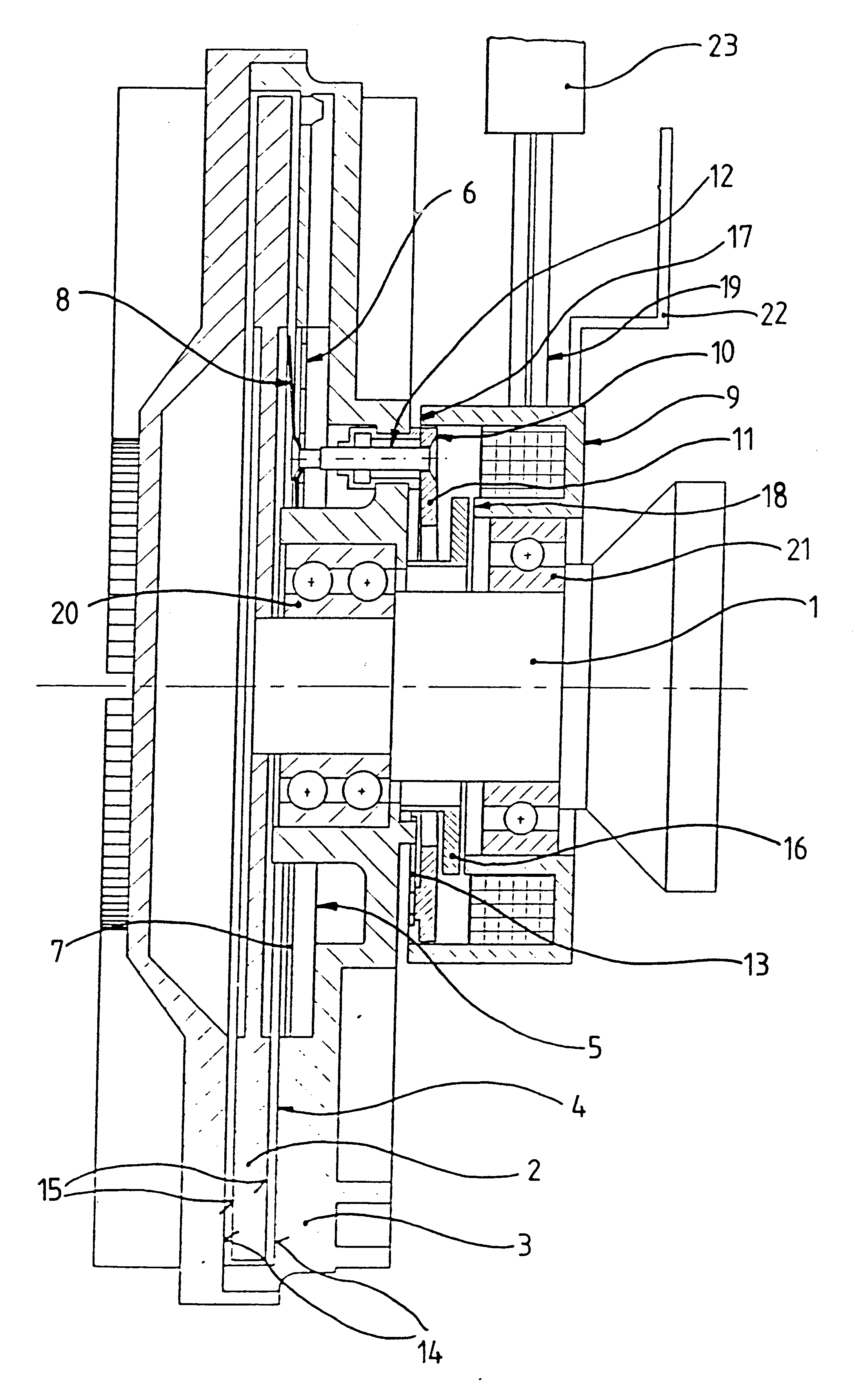
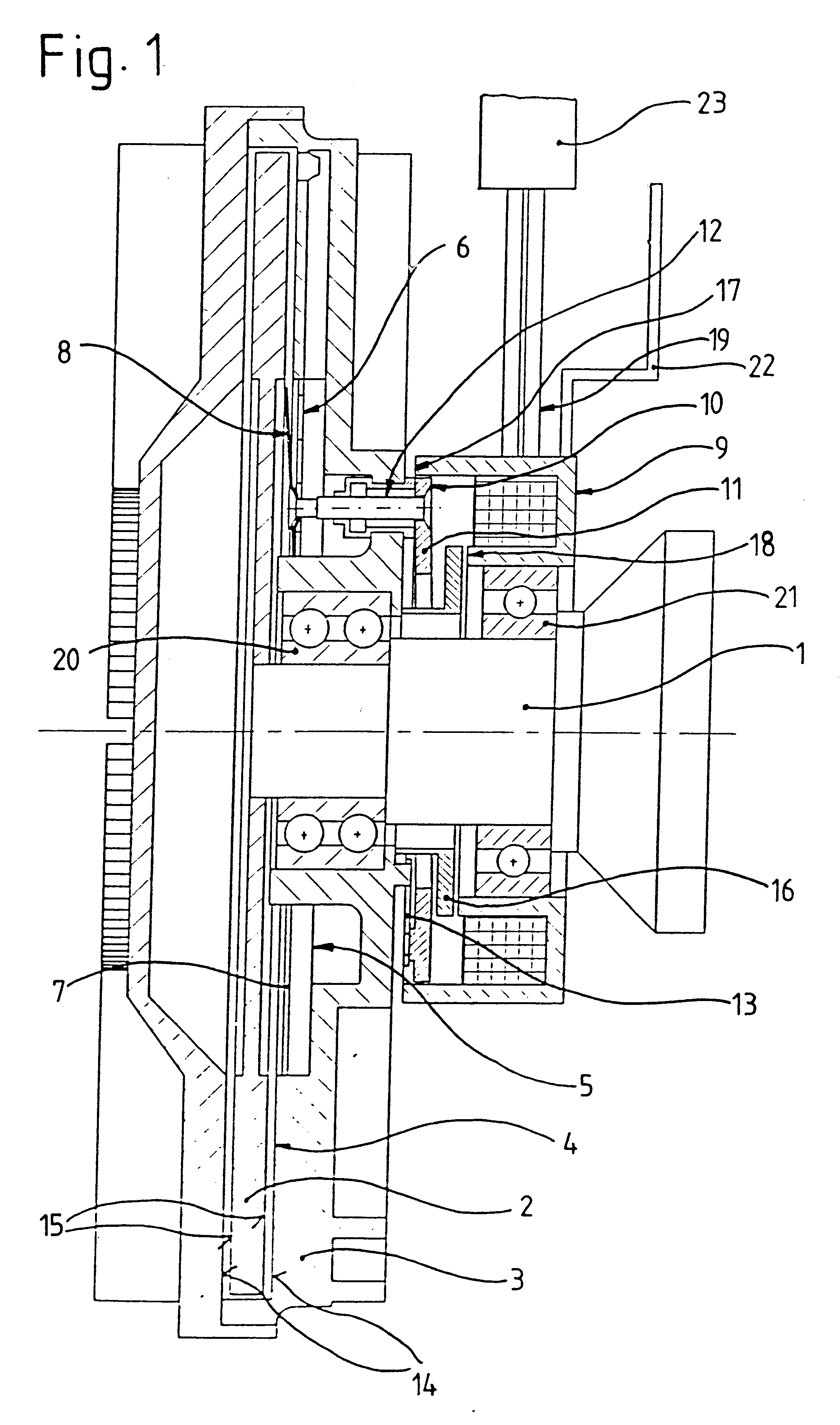
A fluid friction coupling according to an embodiment of the present invention is shown in FIG. 1 for a fan drive of a motor vehicle. The fluid friction coupling includes a housing 3 and a drive disk 2 driven by a drive shaft 1. The drive shaft 1 may, for example, comprise a crankshaft or a camshaft of an internal combustion engine. Fan blades may be fastened to the housing 3 for conveying cooling air when the housing is rotated via transmission of torque between the drive disk 2 and the housing 3.

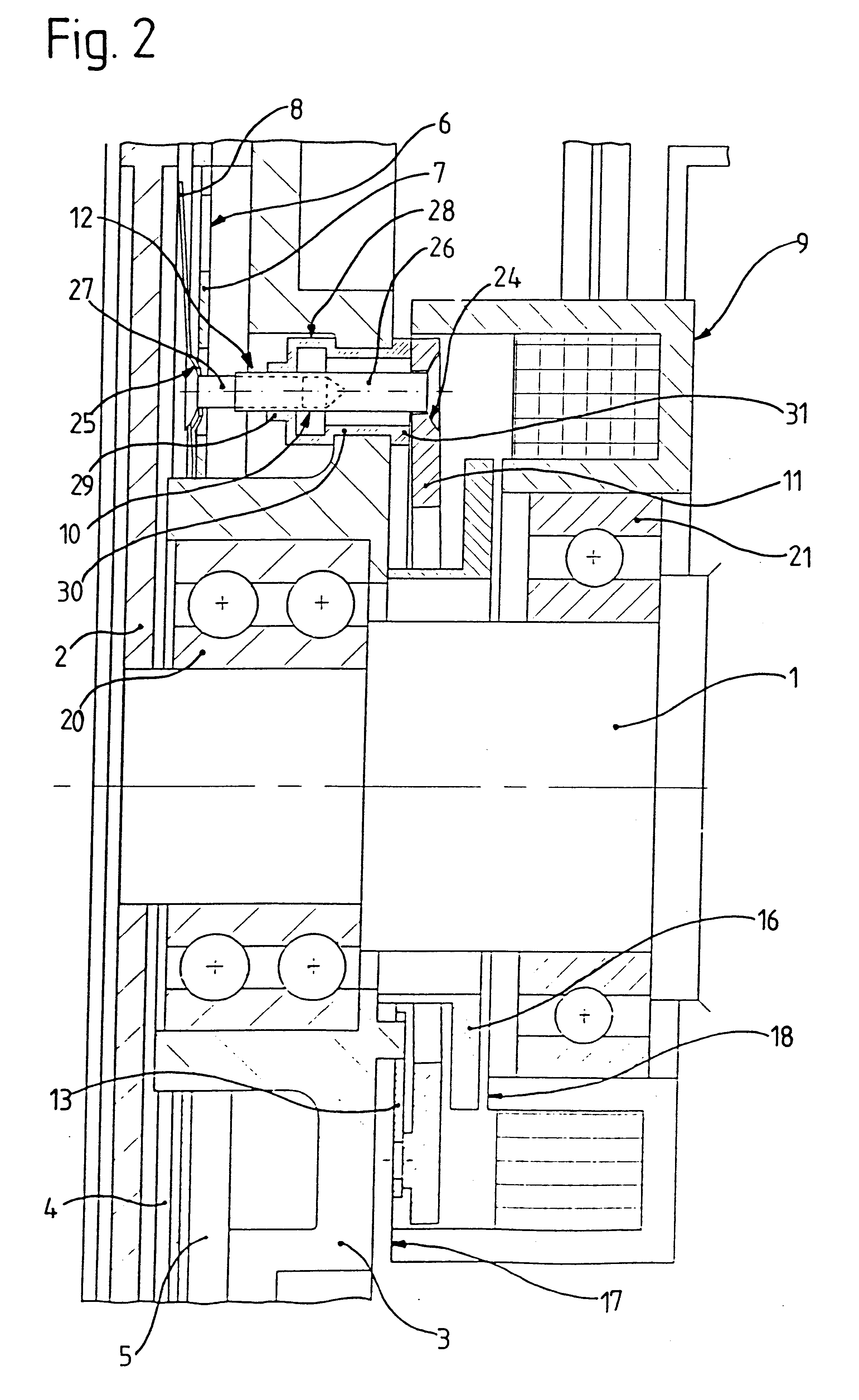
The drive disk 2 is arranged in the housing 3 which also includes a working chamber 4 and a supply chamber 5 for viscous fluid. The working chamber 4 and the supply chamber 5 are separated from each other by a partition 7 having a connection opening 6 arranged therethrough. A single connection opening 6 is illustrated in the drawing. Of course, the partition 7 may also have a plurality of connection openings 6. When the connection opening 6 is released, viscous fluid passes from the supply ...


PUM


Abstract

A fluid friction coupling for driving a fan of an internal combustion engine includes a solenoid configured such that it surrounds a drive shaft and is operatively arranged for moving a control part. The control part moves a valve body which controls the flow of a viscous fluid into a working chamber. The fluid friction coupling is of particularly compact configuration and magnetic losses are kept particularly low.

Description

1. Field of the InventionThe invention relates to a fluid friction coupling for transmitting a torque from a drive shaft to a further component, more specifically a fan of an internal combustion engine of a motor vehicle, via a viscous fluid level in a working chamber in the further component, the fluid friction coupling including a supply chamber for viscous fluid with a partition having a connection opening arranged between the working chamber and the supply chamber and a valve body operatively arranged for releasing or closing the connection opening via a solenoid.2. Description of the Related ArtA fluid friction coupling is disclosed in DE 196 45 478 A1 for transmitting torque via a viscous fluid level in a working chamber with a valve body arranged between the working chamber and a supply chamber. The valve body is operable via a solenoid for opening or closing a connection opening between the supply chamber and working chamber. In this fluid friction coupling, the valve body i...

Claims


Application Information

Patent Timeline
IPC IPC(8): F01P7/04F01P7/00F16K31/06F16D35/02F16D35/00
CPCF01P7/042F16D35/02F16K31/0644F16K31/0689F16D35/024
Inventor KRAMMER, RAIMUND
Owner MANNESMANN SACHS AG
Why Eureka
Try Eureka