Rekeyable padlock with a lock cylinder having an enlarged viewing slot

a locking cylinder and padlock technology, applied in padlocks, building locks, constructions, etc., can solve the problems of user forgetting the combination, inability to open the padlock, and many problems with combination padlocks, so as to achieve greater ease of placement of pins, easy detection, and greater visibility

Inactive Publication Date: 2002-07-30
ABUS AUGUST BREMICKER SOEHNE AG
View PDF11 Cites 85 Cited by
  • Summary
  • Abstract
  • Description
  • Claims
  • Application Information

AI Technical Summary

Benefits of technology

According to a preferred embodiment of the present invention, a rekeyable padlock is provided with a lock cylinder formed within. The lock cylinder includes a cylindrical core formed to receive a key and an outer casing formed around the core. A viewing opening is formed within the casing wall, the viewing opening allowing access to pin openings formed within the core to receive selected pins. T

Problems solved by technology

However, several problems may occur with combination padlocks.
The user may forget the combination, and, therefore, be unable to open the padlock.
The user may write down the combination, which could compromise the security of the lock.
In addition, if the lock is not used often, the user may forget where the written combination was stored.
Storing the padlock key increases the risk that the user will forget where the padlock key is stored or that the padlock key will not be found again.
Carrying the padlock key with other commonly used keys, however, increases the bulk of the user's key chain and can be a source of irritation if the user has multiple padlock keys for multiple padlocks.
As the pins become smaller and as the number of pins used and the number of variations of pin lengths increases, however, the more difficult it becomes to differentiate pins having the different pin lengths.
The relatively small size of the pins, in addition to the small differences in length of the p

Method used


Image

  • Rekeyable padlock with a lock cylinder having an enlarged viewing slot
  • Rekeyable padlock with a lock cylinder having an enlarged viewing slot
  • Rekeyable padlock with a lock cylinder having an enlarged viewing slot

Examples


Embodiment Construction

Referring now to the several drawing figures in which identical elements are numbered identically throughout, a description of the preferred embodiments will now be provided. In providing such a description, specific methods and parts of the invention will be described. It will be appreciated that variants (some of which will be later described) of such specifics are intended to be included within the scope of the appended claims.

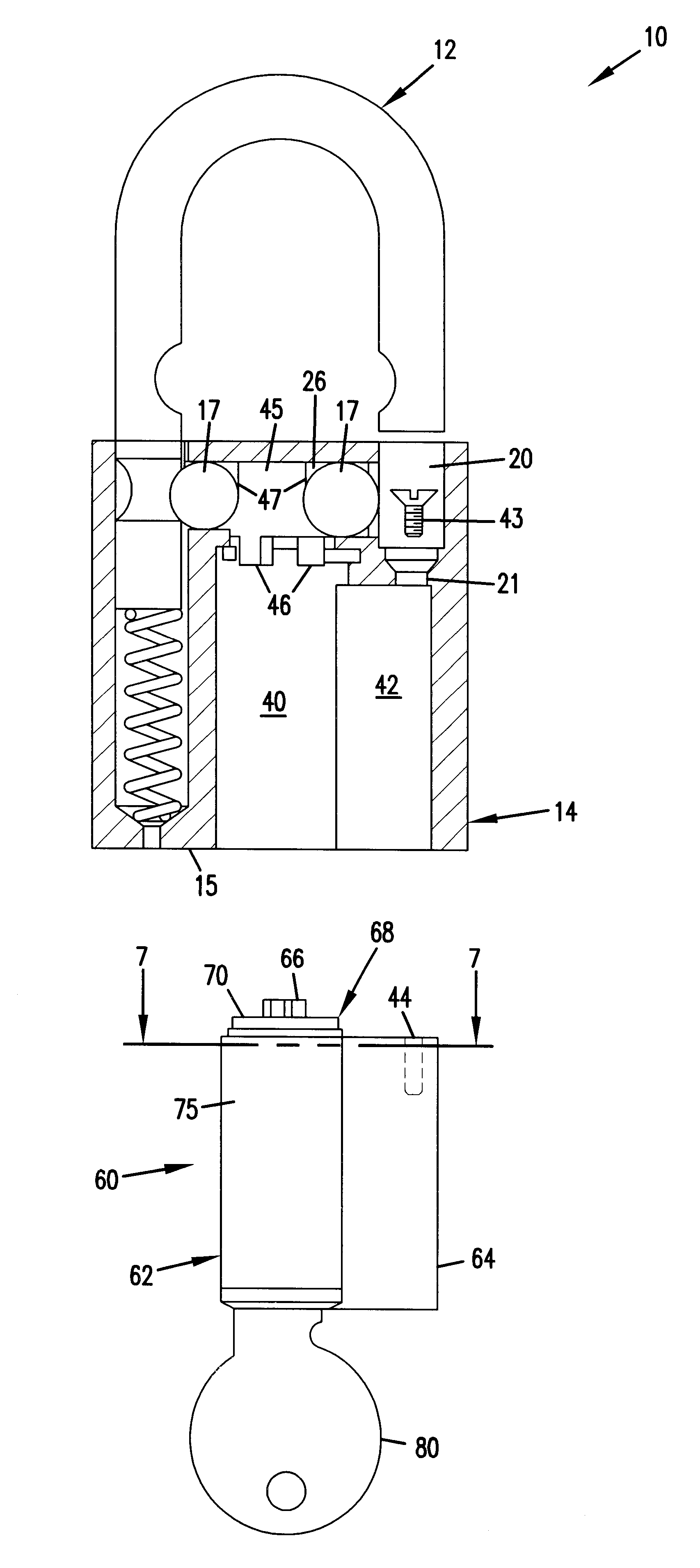
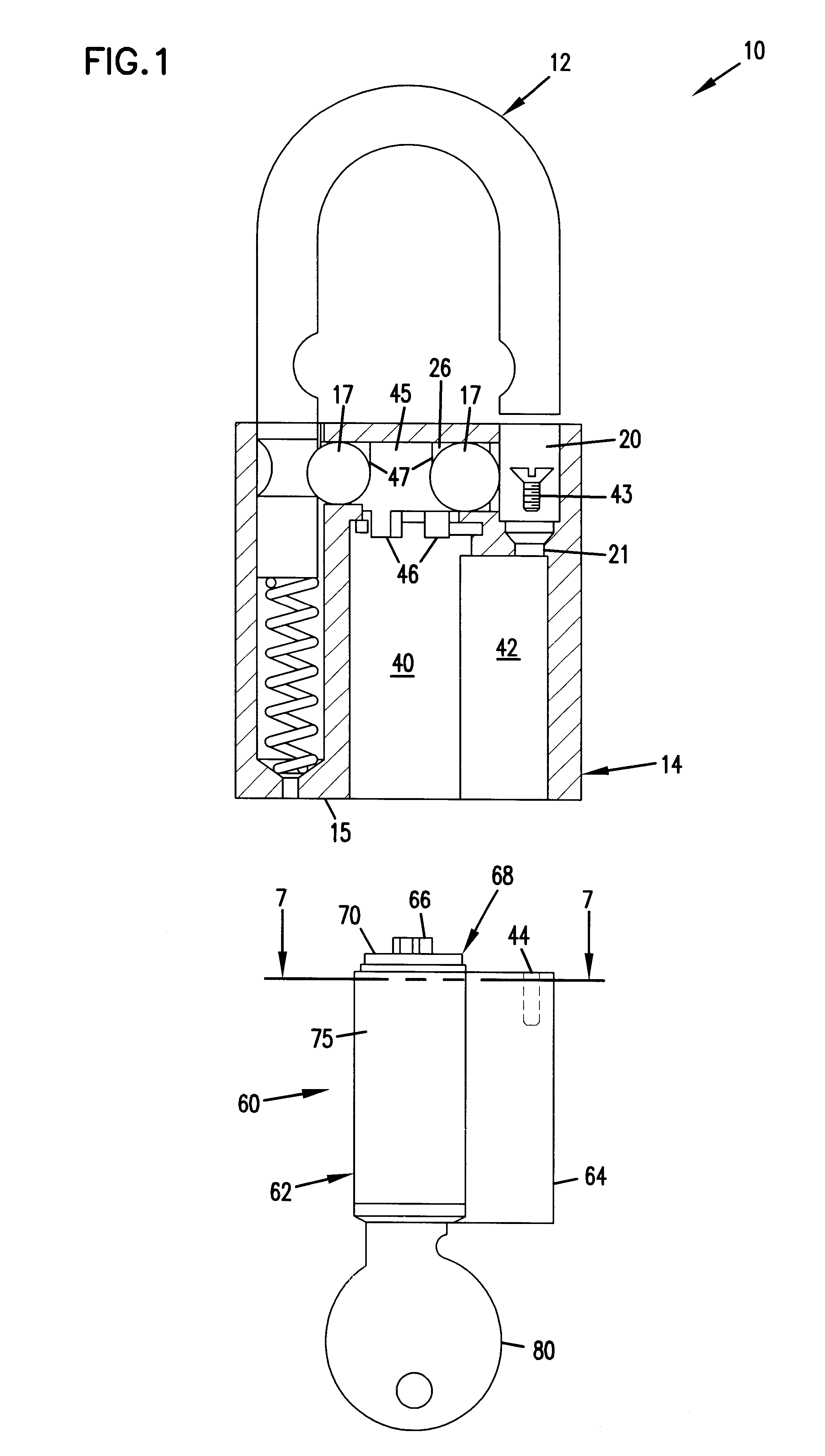
Referring to FIG. 1, a rekeyable padlock 10 is shown. The padlock shown has a padlock body 14 with generally the same configuration as the ones described in U.S. Pat. Nos. 5,363,678 and 5,377,511, previously incorporated by reference herein. A description of the padlock 10, shown in FIG. 1 follows. However, it will be apparent that a variety of configurations of the actual padlock body 14 can by used in accordance with the present invention.

The padlock 10 includes a U-shaped shackle 12 and a removable lock cylinder 60 that fits within the padlock body 14. T...


PUM


Abstract

This invention pertains to the lock cylinder of a rekeyable padlock. According to a preferred embodiment of the present invention, a rekeyable padlock is provided with a lock cylinder formed within. The lock cylinder includes a cylindrical core formed to receive a key and an outer casing formed around the core. A viewing opening is formed within the casing wall, the viewing opening allowing access to pin openings formed within the core to receive selected pins. The viewing opening is shaped such that it provides a viewing area larger than the pin openings, thereby allowing greater visibility when the pins are placed within the pin openings. The advantages of this viewing opening include greater ease in placing the pins into the pin openings and easier detection when a selected pin is the wrong length and does not sit flush within the lock cylinder core.

Description

I. BACKGROUND OF THE INVENTION1. Field of the InventionThis invention pertains to padlocks. More particularly, this invention pertains to the lock cylinder of a rekeyable padlock.2. Description of the Prior ArtPadlocks are commonly used to secure belongings in structures such as sheds, trunks, lock boxes, and the like. One type of padlock is a combination padlock in which a combination (i.e., a unique code typically represented by numbers) is used to unlock the padlock. However, several problems may occur with combination padlocks. The user may forget the combination, and, therefore, be unable to open the padlock. The user may write down the combination, which could compromise the security of the lock. In addition, if the lock is not used often, the user may forget where the written combination was stored.A keyable padlock is another common type of padlock. Keyable padlocks are advantageous over combination padlocks because keyable padlocks do not require memorization of a combinati...

Claims


Application Information

Patent Timeline
IPC IPC(8): E05B67/00E05B67/24E05B29/00E05B9/00E05B9/08
CPCE05B67/24E05B9/084E05B27/005Y10T70/487Y10T70/7107Y10T70/774Y10T70/7768Y10T70/7797Y10T70/7864
Inventor LAITALA, DANIEL A.LAITALA, GRANT T.
Owner ABUS AUGUST BREMICKER SOEHNE AG
Why Eureka
Try Eureka