
Sealing arrangement between two components rotating relative to one another

a technology of rotating components and sealing arrangements, applied in the direction of engine seals, engine components, mechanical apparatus, etc., can solve the problems of space-saving construction and easy mounting as well

Inactive Publication Date: 2002-09-03
VOITH PATENT GMBH +1
View PDF10 Cites 17 Cited by
  • Summary
  • Abstract
  • Description
  • Claims
  • Application Information

AI Technical Summary

Benefits of technology

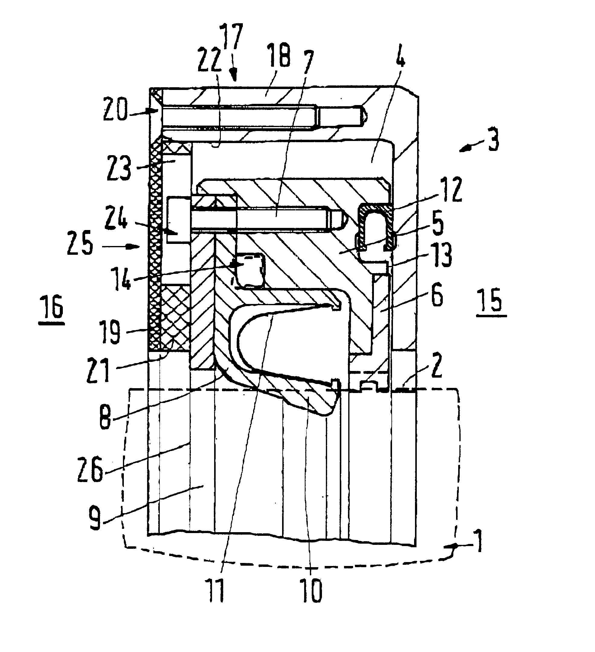
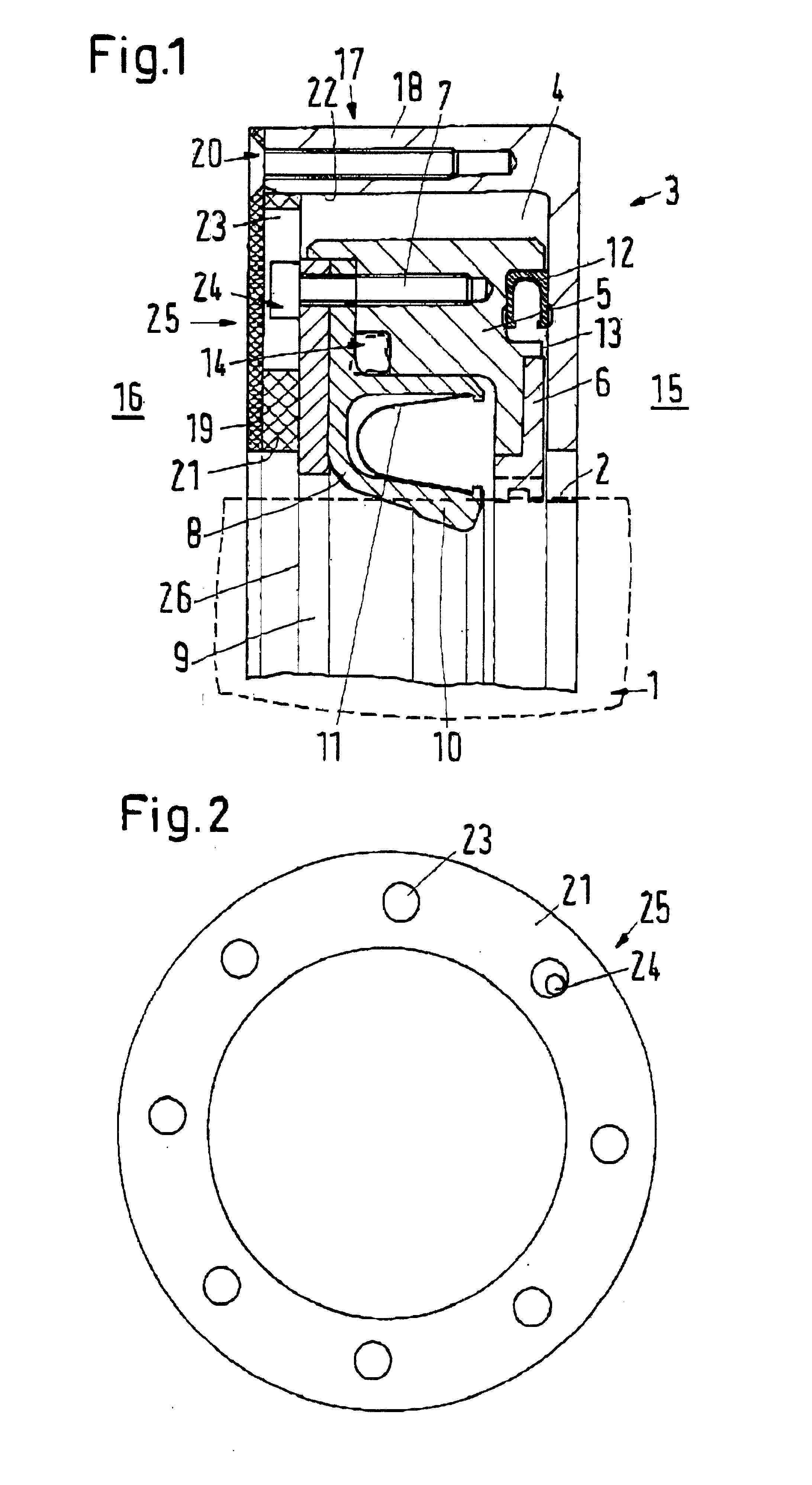
This anti-twisting device allows the radial sealing lips to press against the circumferential surface with greater force, whether by oil pressure or constructive measures, without the danger that the ring-shaped carrier and the ring groove will rotate relative to one another. Nonetheless, the free movement between the carrier and ring groove, as it is necessary to maintain the sealing effect in the case of components being displaced relative to one another, is substantially guaranteed.
Moreover, it is favorable for the radial lip of the radial lip seal to be loaded by a spring in the direction of the circumferential surface. In this manner, the pressing force of the radial lip can be increased, which is desirable in many cases and is also permissible because of the anti-twisting device claimed.

Problems solved by technology

This leads to a space-saving construction.
Mounting is uncomplicated as well.

Method used


Image

  • Sealing arrangement between two components rotating relative to one another
  • Sealing arrangement between two components rotating relative to one another

Examples


Embodiment Construction

The particulars shown herein are by way of example and for purposes of illustrative discussion of the embodiments of the present invention only and are presented in the cause of providing what is believed to be the most useful and readily understood description of the principles and conceptual aspects of the present invention. In this regard, no attempt is made to show structural details of the present invention in more detail than is necessary for the fundamental understanding of the present invention, the description taken with the drawings making apparent to those skilled in the art how the several forms of the present invention may be embodied in practice.

In FIG. 1, a first component 1 with a cylindrical circumferential surface 2 is shown in dashed lines. A second component 3 has a ring groove 4 in which a carrier 5 can be mounted. Carrier 5 has a limited axial play in ring groove 4 and is supported on circumferential surface 2 by way of a centering rod 6. With the aid of a numb...


PUM


Abstract

Sealing arrangement between relatively rotatable components that includes a first component having a cylindrical circumferential surface on one of an interior and exterior circumference, and a second component having a ring groove open toward the circumferential surface. A ring-shaped carrier is arranged to be displaceable in the ring groove, a centering rod is arranged to guide the ring-shaped carrier on the circumferential surface, and a radial lip seal is arranged to rest against the circumferential surface in an elastic manner. An axial seal is arranged to rest against a side wall of the ring groove, and an anti-twisting device is coupled to the ring-shaped carrier and arranged to enable a limited range of motion in all directions of a radial plane.

Description

The present application claims priority under 35 U.S.C. .sctn. 119 of German Patent Application No. 100 00 541.1, filed on Jan. 8, 2000, the disclosure of which is expressly incorporated by reference herein in its entirety.1. Field of the inventionThe invention relates to a sealing arrangement between two components rotating relative to one another. The first component has a cylindrical circumferential surface on its inner or outer circumference and the second component has a ring groove open to the circumferential surface. A ring-shaped carrier is displaceable in the ring groove, and is guided on the circumferential surface by a centering rod. The carrier includes a radial lip seal whose lips rest against the circumferential surface in an elastic manner, and carries an axial seal that rests against a side wall of the ring groove.2. Discussion of Background InformationSuch a sealing arrangement is known, e.g., from DE 198 09 303 A1. Due to the displaceable nature of the carrier in t...

Claims


Application Information

Patent Timeline
Patent Type & Authority Patents(United States)
IPC IPC(8): F16J15/44F16J15/32F16J15/3224F16J15/3236
CPCF16J15/3224F16J15/3236F16J15/441
Inventor LEBEAU, FRANCISWENZEL, REINHARD
Owner VOITH PATENT GMBH
Learn More