

Biopsy forceps for endoscope
a technology of endoscope and forceps, which is applied in the field of biopsy forceps, can solve the problems of profuse bleeding, unnecessarily large wounds, and tissue fragments being cut off from the mucous membrane,
- Summary
- Abstract
- Description
- Claims
- Application Information
AI Technical Summary
Problems solved by technology
Method used
Image

Examples
first embodiment
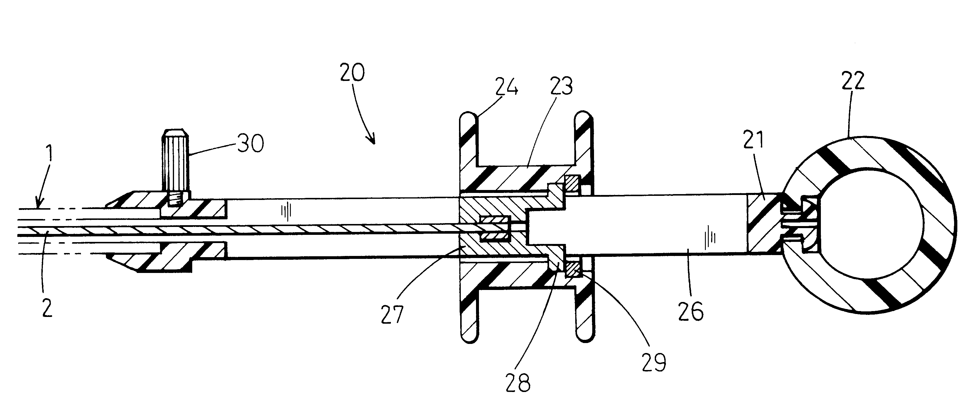
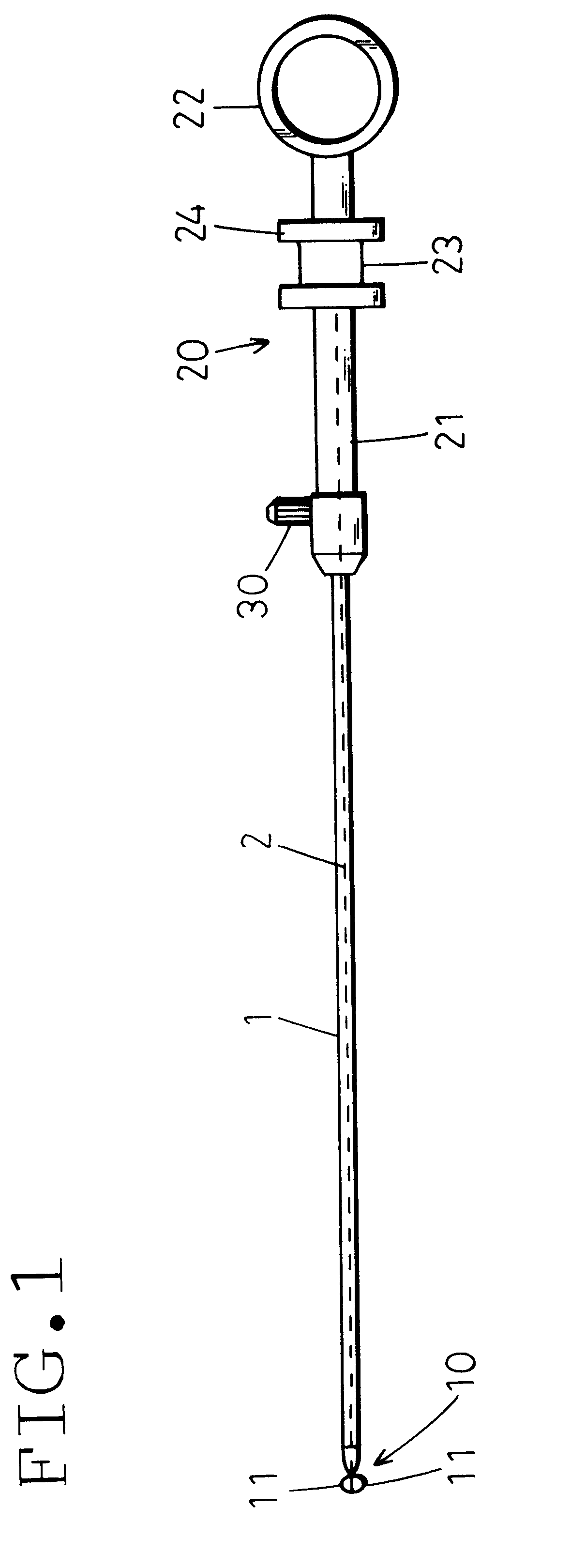
FIG. 1 shows a biopsy forceps for an endoscope according to the present invention. A flexible sheath 1 is removably inserted into an instrument guide tube (instrument-inserting channel) of an endoscope (not shown). A control wire 2 is axially movably inserted in the sheath 1 over the entire length thereof.
A control part 20 for advancing or retracting the control wire 2 is connected to the proximal end of the sheath 1. A distal end operating part 10 is connected to the distal end of the sheath 1. The distal end operating part 10 is driven by the control wire 2.
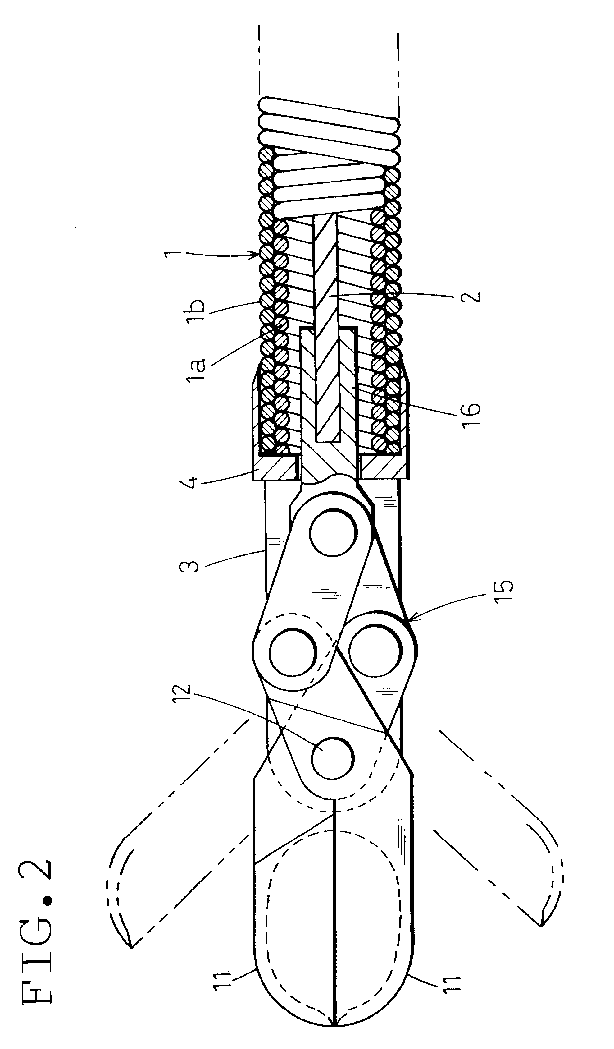
FIG. 2 shows the distal end operating part 10. A distal end block 4 is firmly connected to the distal end of the sheath 1. The distal end block 4 has a large slit 3 cut from the forward end thereof. A pivot shaft 12 is mounted on the distal end block 4 in such a way as to cross the distal end portion of the slit 3.
A pair of forceps cups 11 are rotatably supported by the pivot shaft 12 so as to open or close in a beaklike manner...
second embodiment
In the second embodiment, a pair of engaging projections 28 are formed on the wire retainer 27 in 180-degree symmetric relation to each other. The slider 23 is integrally formed with the second finger engagement portion 24. The engaging projections 28 and the slider 23 are in thread engagement with each other.
The slider 23 has a threaded portion 31 that uses a double thread having thread grooves cut in two rows. An axially compressed coil spring 32 is fitted to the threaded portion 31. A rotation control pin 30 or the like as provided on the control part body 21 in the first embodiment is not provided in the second embodiment.
In the second embodiment with the described arrangement, when the second finger engagement portion 24 is drawn toward the first finger engagement portion 22, first, the control wire 2 is pulled without causing the coil spring 32 to contract. Consequently, the pair of forceps cups 11 are closed to bite the mucous membrane.
When the second finger engagement portio...
third embodiment
FIG. 5 shows the present invention, in which a rotation control ring 33 secured to the proximal end of the sheath 1 is connected to a distal end portion 21a of the control part body 21 so as to be rotatable about the axis of the control part body 21. The first finger engagement portion 22 and the second finger engagement portion 24 need not be rotatable relative to the control part body 21.
By virtue of the above-described arrangement, rotating the rotation control ring 33 about the axis of the control part body 21 allows only the sheath 1 to rotate without causing the control part 20 to rotate, thereby rotating the forceps cups 11 at the distal end of the sheath 1. In this case, the sheath 1 and the control wire 2 may twist relative to each other. Therefore, it is desirable to use a stranded wire as the control wire 2.
According to the present invention, a piece of tissue for a biopsy specimen can be taken from the mucous membrane by rotating a pair of forceps cups through the sheath...
PUM
 Abstract
Description
Claims
Application Information