Vacuum switch operating mechanism including laminated flexible shunt connector

a flexible shunt and vacuum switch technology, applied in the direction of air-break switch, high-tension/heavy-dress switch, contacts, etc., can solve the problems of long conductor, large space in two dimensions, and long shun

Inactive Publication Date: 2002-09-03
EATON INTELLIGENT POWER LIMITED
View PDF7 Cites 21 Cited by
  • Summary
  • Abstract
  • Description
  • Claims
  • Application Information

AI Technical Summary

Problems solved by technology

In some applications, the laminated shunt is installed in a C configuration which requires a long conductor and takes considerable space in two dimensions.
This latter arrangement is very effective, but again, requires a long shunt and considerable space in two dimensions.
The currently available flexible conductors or shunts have been found to be either too large, too expensive, not reliable enough or require too much force to oper

Method used


Image

  • Vacuum switch operating mechanism including laminated flexible shunt connector
  • Vacuum switch operating mechanism including laminated flexible shunt connector
  • Vacuum switch operating mechanism including laminated flexible shunt connector

Examples


Embodiment Construction

Tests were conducted on a flexible shunt in accordance with the invention with the following specifications:

1,250 amps continuous current

25 KA symmetrical for three seconds

63 KA peak

20 mm total motion (+ / -10 mm from neutral axis)

must have low resistance and maintain low resistance, including joints

must be economical to produce and use

must not be deformed or damaged by high transient currents

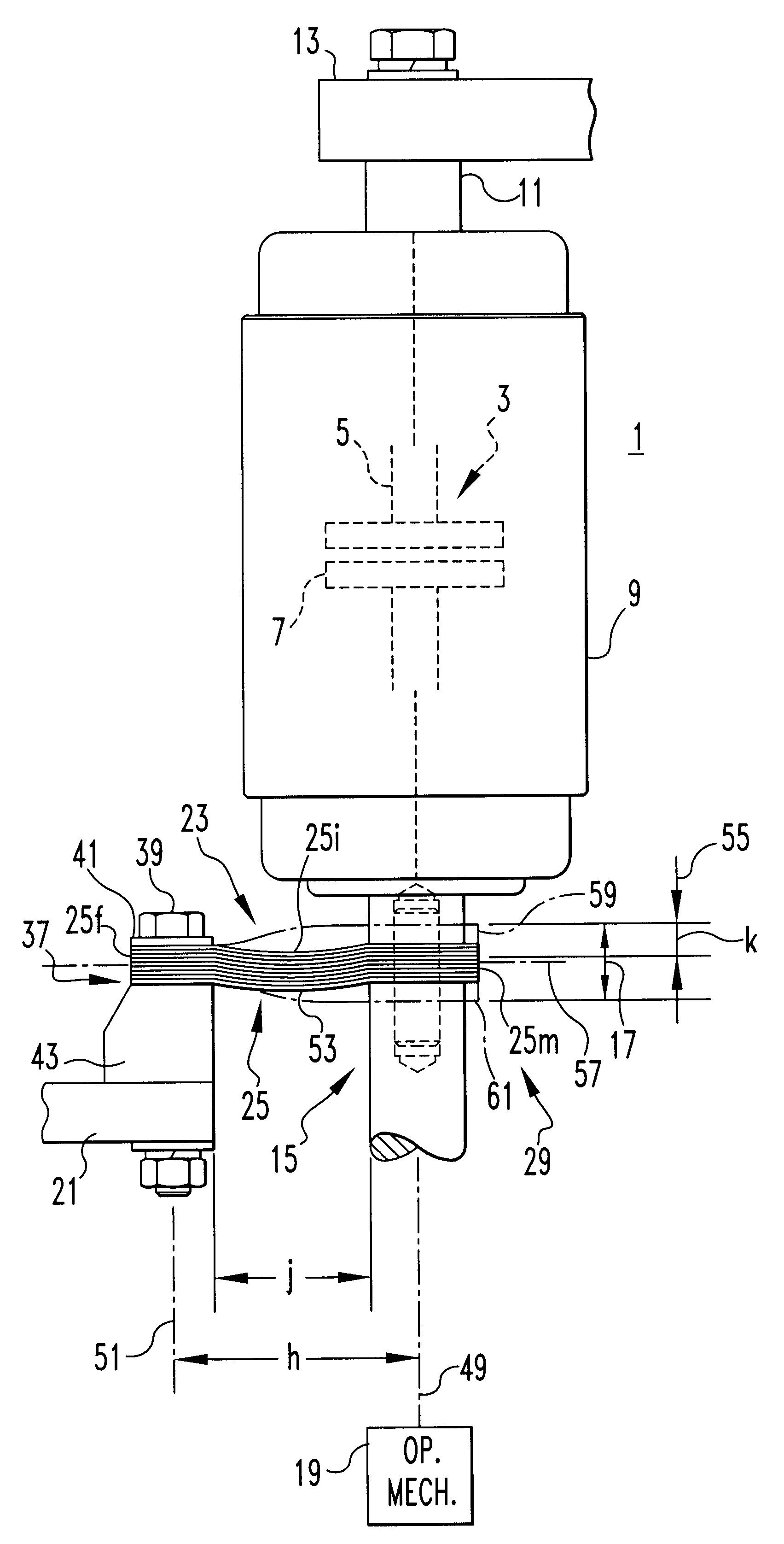
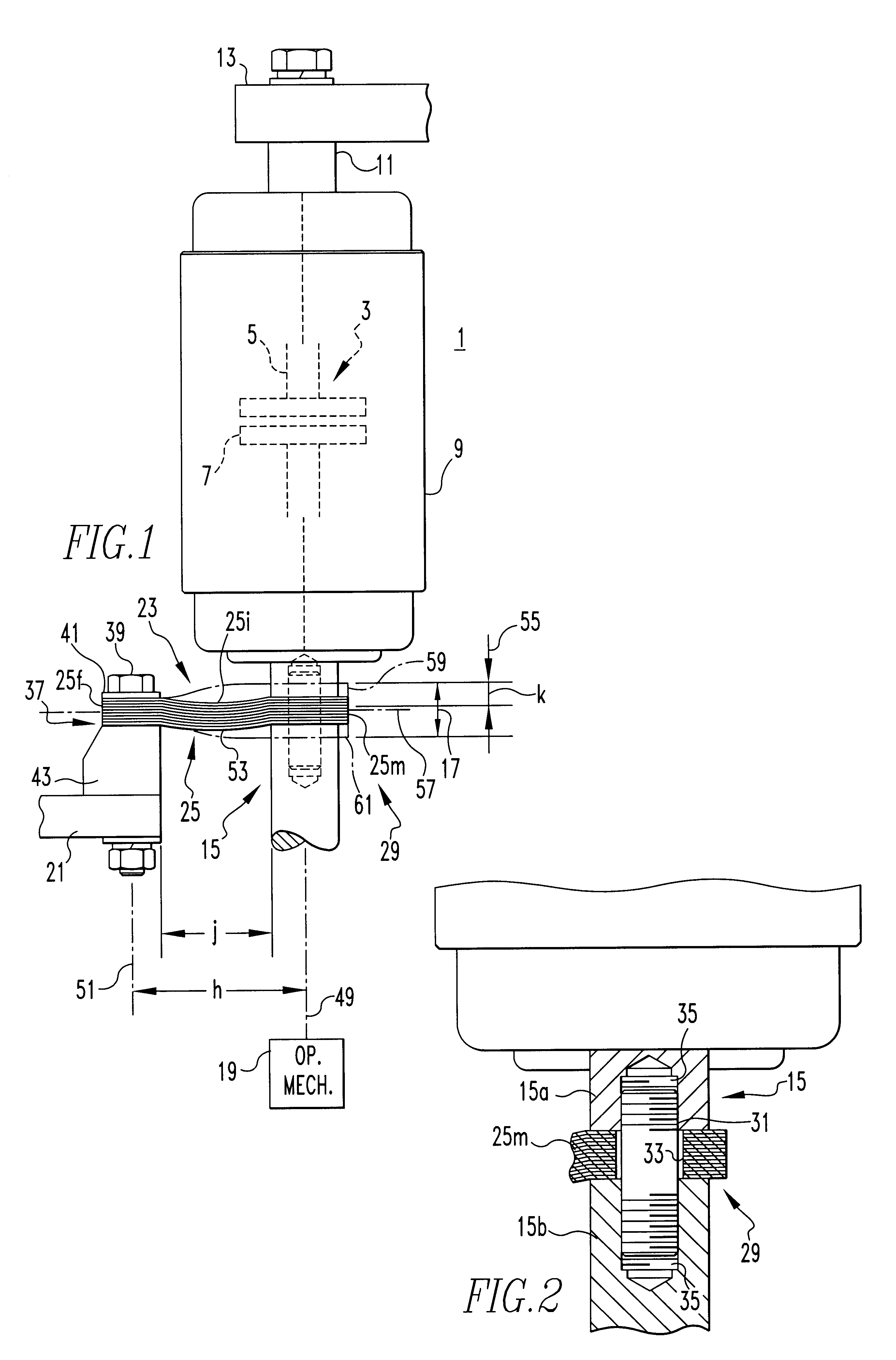
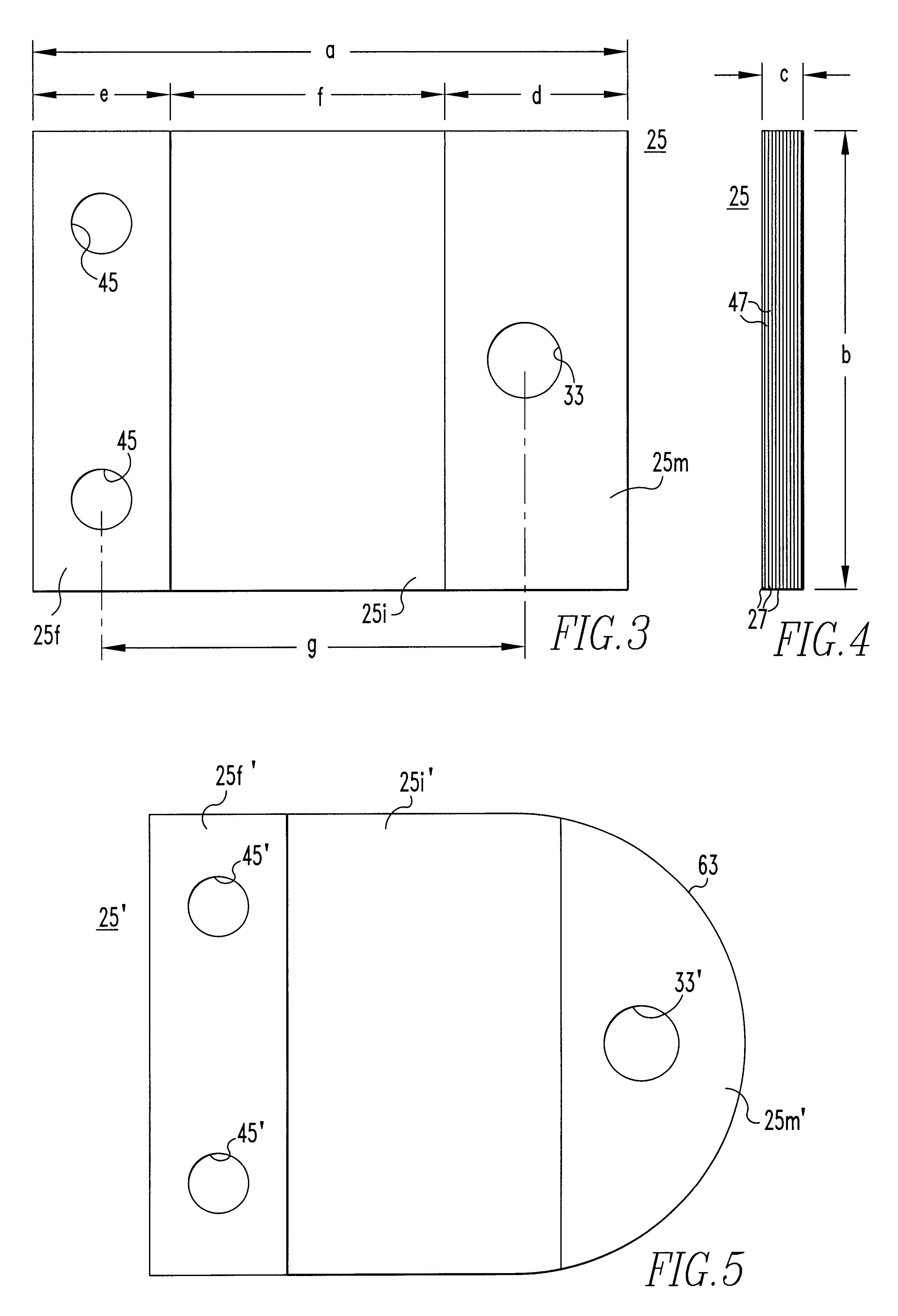
The width "b" of the flexible member 25 was set at 2.5 inch (63.5 mm) to accommodate a particular vacuum interrupter construction. A cross sectional area ("b".times."c") of 0.9 square inches (5.81 cm.sup.2) resulted in a current density at a rated current of 1,250 amps of 1,390 amps per in.sup.2 (215 A / cm.sup.2). With the width "b" of 2.5 inch (63.5 mm) the thickness "c" is 0.36 inch (9.1 mm). Using 0.0015 foil (with plating), 240 laminations were stacked up.

The full length "a" of the laminations was 3.25 inch (8.255 cm), the intermediate length "f" was 1.5 inch (38.1 mm). Through experimentation...


PUM


Abstract

A flexible shunt in the form of a flexible member made up of a stack of electrically conductive laminations each of a thickness of no more than about 0.002 inch (0.051 mm) has a moveable end secured by a moveable mount to a moveable contact support of an electric power switch for movement along a linear path. A fixed mount secures the fixed end of the flexible member to a fixed conductor termination spaced laterally from the moveable end along a neutral axis perpendicular to the linear path of the moveable end by an offset distance such that the installed length of the intermediate section between the fixed and moveable ends is less than the free length of the intermediate section. With this arrangement the stroke of the moveable end along the linear path can be up to at least ⅓ and even ½ of the free length of the intermediate section of the flexible member and with very low operating forces.

Description

1. Field of the InventionThis invention relates to flexible connections for conducting load current in electric power switches between a moveable contact support and a fixed conductor.2. Background InformationElectric power switches require an arrangement for conducting the load current between a moveable contact of the switch and a fixed conductor. The requirements for such an arrangement are many and include such things as: adequate current carrying capability, adequate motion capacity and directional ability, minimum force / energy requirements, temperature withstand ability, ability to retain shape or integrity under transient conditions, and others. While some electric power switches utilize sliding connectors for this purpose, the most common connection is a flexible conductor or shunt.In electric power switches with lower current ratings, a braided copper conductor is often used as the flexible shunt. At higher current ratings, such as in medium voltage circuit breakers, it is ...

Claims


Application Information

Patent Timeline
IPC IPC(8): H01H1/00H01H1/58H01H33/66
CPCH01H1/5822H01H33/66H01H33/6606H01H2001/5827H01H2033/6613
Inventor CROOKSTON, RONALD W.HOEGLE, JOHN J.BOTTEGAL, PAUL T.JENKINS, WALTER O.MARCHAND, FRANCOIS J.
Owner EATON INTELLIGENT POWER LIMITED
Why Eureka
Try Eureka