Phased array antenna with active parasitic elements
a phased array and parasitic element technology, applied in the field of antennas, can solve problems such as wasting antenna real esta
- Summary
- Abstract
- Description
- Claims
- Application Information
AI Technical Summary
Problems solved by technology
Method used
Image

Examples
Embodiment Construction
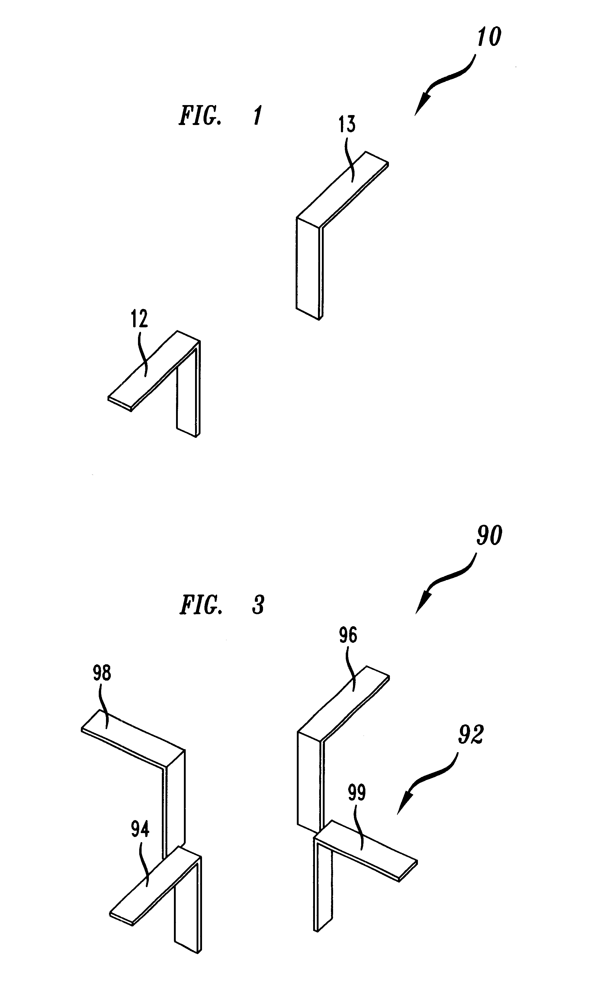
FIG. 1 illustrates dipole element 10 where signals are fed to and received from the element at points 12 and / or 13. If an unbalanced configuration is used, signals are fed to and received from point 12, and point 13 is typically grounded. If a balanced configuration is used, signals that are 180 degrees out of phase with respect to each other are fed to and received from points 12 and 13.
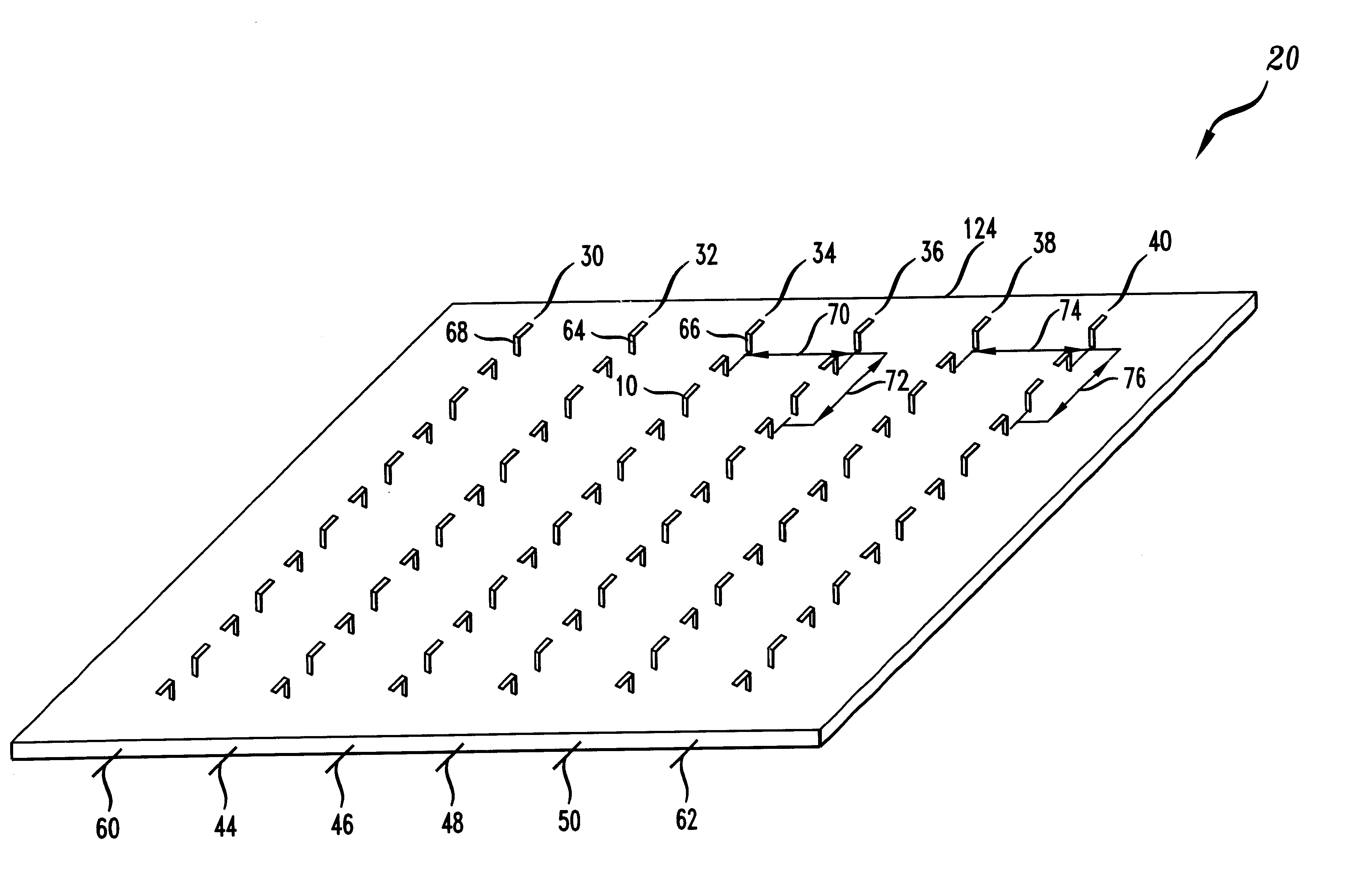
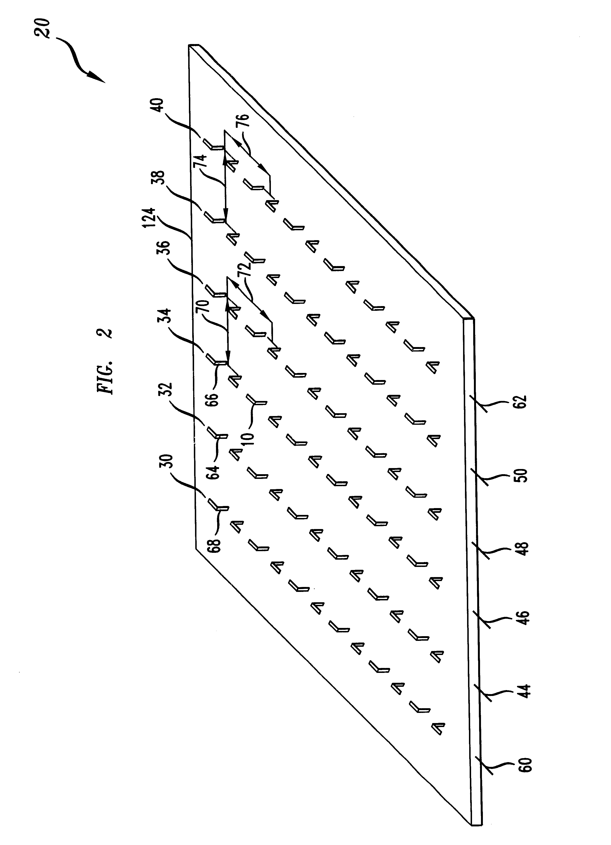
FIG. 2 illustrates antenna 20 that includes active or beam forming array antenna elements and active parasitic elements. Dipole antenna elements 10 are arranged in columns 30, 32, 34, 36, 38 and 40, and have similar polarizations. The elements of columns 32, 34, 36 and 38 compose the active or beam forming array portion of antenna 20. It should be noted that a four column by six row array is being shown for illustrative purposes and that other size arrays may be used. Signals to and from the elements of columns 32, 34, 36 and 38 may be conducted via corporate feed patterns or networks connected to l...
PUM
 Abstract
Description
Claims
Application Information
 - R&D
- Intellectual Property
- Life Sciences
- Materials
- Tech Scout
- Unparalleled Data Quality
- Higher Quality Content
- 60% Fewer Hallucinations
Browse by: Latest US Patents, China's latest patents, Technical Efficacy Thesaurus, Application Domain, Technology Topic, Popular Technical Reports.
© 2025 PatSnap. All rights reserved.Legal|Privacy policy|Modern Slavery Act Transparency Statement|Sitemap|About US| Contact US: help@patsnap.com